MAIN BODY ECU REMOVAL
PROCEDURE
-
PRECAUTION
Note
After turning the power switch off, waiting time may be required before disconnecting the cable from the negative (-) auxiliary battery terminal. Therefore, make sure to read the disconnecting the cable from the negative (-) auxiliary battery terminal notices before proceeding with work Click here.
-
REMOVE DECK BOARD ASSEMBLY
-
REMOVE NO. 1 DECK BOARD
-
REMOVE NO. 2 DECK BOARD
-
REMOVE REAR DECK FLOOR BOX
-
REMOVE DECK FLOOR BOX RH
-
DISCONNECT CABLE FROM NEGATIVE AUXILIARY BATTERY TERMINAL
Note
When disconnecting the cable, some systems need to be initialized after the cable is reconnected Click here.
-
REMOVE NO. 1 INSTRUMENT PANEL UNDER COVER SUB-ASSEMBLY (for LHD)
-
REMOVE LOWER INSTRUMENT PANEL FINISH PANEL ASSEMBLY (for LHD)
-
REMOVE NO. 2 INSTRUMENT PANEL UNDER COVER SUB-ASSEMBLY (for RHD)
Tech Tips
Use the same procedure as for LHD Click here.
-
REMOVE GLOVE COMPARTMENT DOOR ASSEMBLY (for RHD)
Tech Tips
Use the same procedure as for LHD Click here.
-
REMOVE ECU INTEGRATION BOX LH (for RHD)
-
REMOVE INSTRUMENT PANEL JUNCTION BLOCK ASSEMBLY
-
for LHD:
-
Disconnect each connector.
-
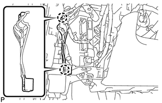
Disengage the claw and disconnect the connector as shown in the illustration.
-
Disengage the claw and disconnect the connector as shown in the illustration.
-
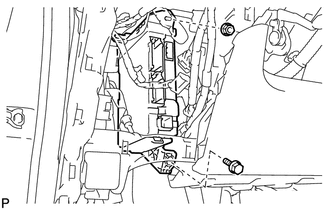
Remove the bolt and nut, and disconnect the instrument panel junction block assembly.
-
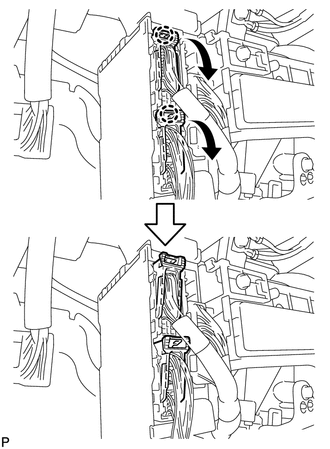
Disengage the 2 claws and disconnect the wiring harness protector.
-
-
for RHD:
-
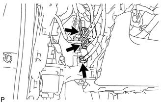
Disengage the 2 claws and disconnect the 2 connectors as shown in the illustration.
-
Disconnect each connector.
-
Disengage the clamp.
-
Remove the bolt and nut, and disconnect the instrument panel junction block assembly.
-
Disengage the clamp.
-
-
Disengage the claw and disconnect the connector as shown in the illustration.
-
Disengage the claw and release the connector lock as shown in the illustration.
-
Disengage the claw and disconnect the connector, and remove the instrument panel junction block assembly.
-
-
REMOVE MAIN BODY ECU (MULTIPLEX NETWORK BODY ECU)
-
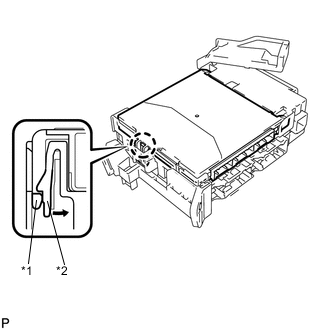
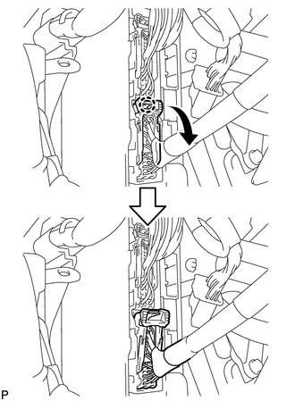
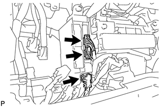
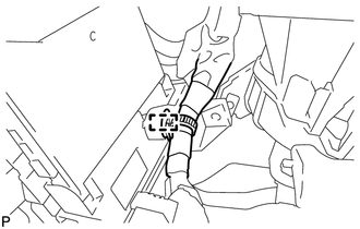
Text in Illustration *1 Main Body ECU (Multiplex Network Body ECU) *2 Claw of Driver Side Junction Block Press the claw of the junction block as shown in the illustration to release the lock.
-
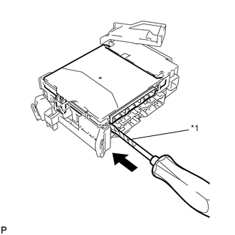
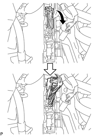
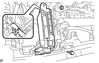
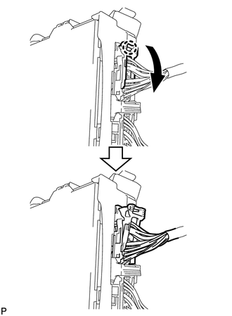
Text in Illustration *1 Protective Tape With the junction block lock released, insert a screwdriver with its tip wrapped with protective tape horizontally between the main body ECU (multiplex network body ECU) and junction block.
Note
Use a screwdriver with a diameter of between 5.0 mm (0.197 in.) and 6.3 mm (0.248 in.) and a length of approximately 90 mm (3.54 in.).
-
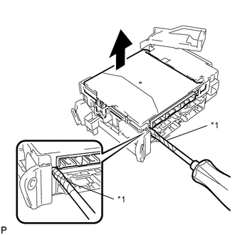
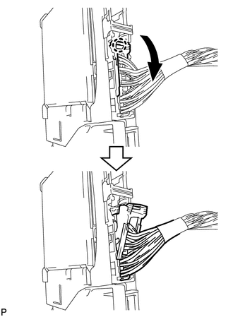
Text in Illustration *1 Protective Tape Using the screwdriver, carefully raise the main body ECU (multiplex network body ECU) up to the position where the connector becomes disengaged.
Note
Do not twist the screwdriver to raise the main body ECU (multiplex network body ECU).
-
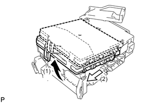
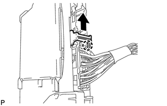
Raise the main body ECU (multiplex network body ECU) as shown by the arrow (1), and then pull it out as shown by the arrow (2) in the illustration.
Note
Do not touch the ECU connector.
-