BACK DOOR ADJUSTMENT
CAUTION / NOTICE / HINT
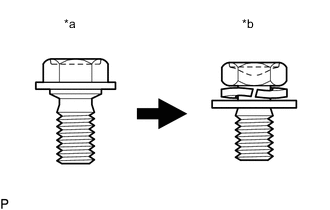
| *a | Centering Bolt |
| *b | Standard Bolt |
Tech Tips
-
Centering bolts are used to install the door hinges to the vehicle body and door. The door cannot be adjusted with the centering bolts installed. Substitute the centering bolts with standard bolts (with washers) when making adjustments.
-
The specified torque for standard bolts is shown in the standard bolt chart.
PROCEDURE
-
INSPECT BACK DOOR
-
Check that the clearance measurements of areas a through g are within each standard range.
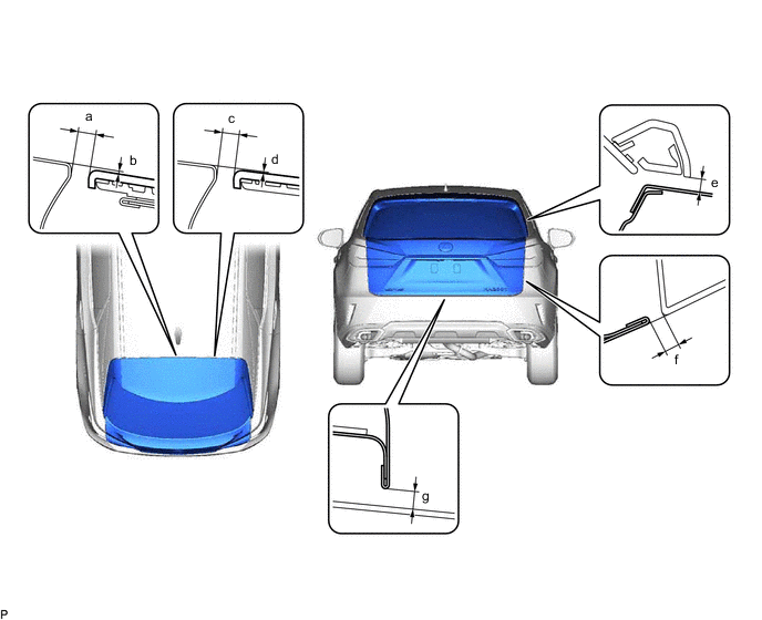
Standard Clearance Area Measurement Area Measurement a 5.95 to 9.95 mm (0.234 to 0.392 in.) b -1.15 to 2.85 mm (-0.0453 to 0.112 in.) c 5.95 to 9.95 mm (0.234 to 0.392 in.) d -1.15 to 2.85 mm (-0.0453 to 0.112 in.) e 3.15 to 7.15 mm (0.124 to 0.281 in.) f 3.85 to 6.85 mm (0.152 to 0.270 in.) g 4.55 to 8.55 mm (0.179 to 0.337 in.) - -
-
-
REMOVE TONNEAU COVER ASSEMBLY
-
REMOVE DECK BOARD ASSEMBLY
-
REMOVE REAR NO. 3 FLOOR BOARD
-
REMOVE SPARE WHEEL COVER (for Compact Spare Tire)
-
REMOVE REAR DECK FLOOR BOX (w/ Spare Tire)
-
REMOVE REAR FLOOR CARPET (w/o Spare Tire)
-
REMOVE REAR NO. 4 FLOOR BOARD (except Full Size Spare Tire)
-
REMOVE REAR NO. 4 FLOOR BOARD (for Full Size Spare Tire)
-
REMOVE DECK SIDE TRIM BOX RH (except Full Size Spare Tire)
-
REMOVE DECK SIDE TRIM BOX RH (for Full Size Spare Tire)
-
REMOVE REAR FLOOR FINISH PLATE
-
ADJUST BACK DOOR
-
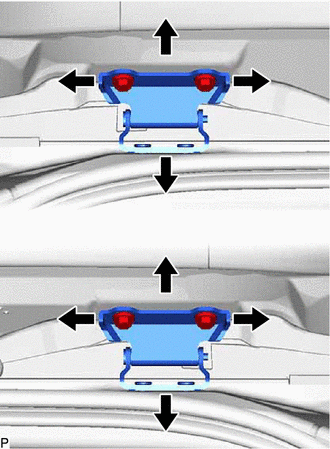
Before adjusting the upper end of the back door up and down or left and right, loosen the 4 hinge bolts on the vehicle body.
-
Tighten the 4 hinge bolts on the vehicle body after adjustment.
- Torque:
- 19.5 N*m { 199 kgf*cm, 14 ft.*lbf }
-
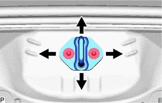
Using a T40 "TORX" socket wrench, slightly loosen the 2 striker mounting screws.
-
Using a brass bar and a hammer, hit the striker to adjust its position.
-
Using a T40 "TORX" socket wrench, tighten the 2 striker mounting screws after adjustment.
- Torque:
- 23 N*m { 235 kgf*cm, 17 ft.*lbf }
-
-
INSTALL REAR FLOOR FINISH PLATE
-
INSTALL DECK SIDE TRIM BOX RH (except Full Size Spare Tire)
-
INSTALL DECK SIDE TRIM BOX RH (for Full Size Spare Tire)
-
INSTALL REAR NO. 4 FLOOR BOARD (except Full Size Spare Tire)
-
INSTALL REAR NO. 4 FLOOR BOARD (for Full Size Spare Tire)
-
INSTALL REAR DECK FLOOR BOX (w/ Spare Tire)
-
INSTALL SPARE WHEEL COVER (for Compact Spare Tire)
-
INSTALL REAR FLOOR CARPET (w/o Spare Tire)
-
INSTALL REAR NO. 3 FLOOR BOARD
-
INSTALL DECK BOARD ASSEMBLY
-
INSTALL TONNEAU COVER ASSEMBLY