MAYDAY SWITCH INSPECTION
PROCEDURE
REMOVE MAP LIGHT ASSEMBLY
INSPECT MAP LIGHT ASSEMBLY
Check the resistance.
-
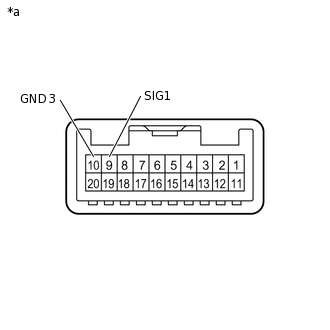
*a
Component without harness connected
(Map Light Assembly)
Measure the resistance according to the value(s) in the table below.
Resistance
Tester Connection
Condition
Specified Condition
9 (SIG1) - 10 (GND3)
Mayday switch not pressed
410 to 414 Ω
9 (SIG1) - 10 (GND3)
Mayday switch pressed
81 to 83 Ω
-
Check the operation (indicator).
-
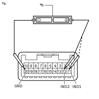
*a
Component without harness connected
(Map Light Assembly)
*b
Two 1.5 V dry cell batteries
Check that each indicator illuminates when 2 dry cell batteries are connected to the map light assembly connector terminals as shown in the illustration.
Note:Do not apply more than 3 V.
OK
Tester Connection
Condition
Specified Condition
11 (IND1) - 20 (GND)
Positive (+) dry cell battery - Negative (-) dry cell battery
HELP RED indicator illuminates
12 (IND2) - 20 (GND)
Positive (+) dry cell battery - Negative (-) dry cell battery
HELP GREEN indicator illuminates
-
-
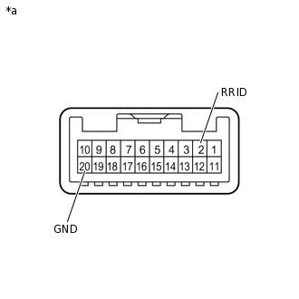
*a
Component without harness connected
(Map Light Assembly)
Check that the HELP indicator illuminates when the battery is connected to the map light assembly connector terminals as shown in the illustration.
OK
Tester Connection
Condition
Specified Condition
2 (RRID) - 20 (GND)
Positive (+) battery terminal - Negative (-) battery terminal
HELP indicator illuminates
INSTALL MAP LIGHT ASSEMBLY