VEHICLE STABILITY CONTROL SYSTEM TRC OFF Indicator Light Remains ON
| DTC Code | DTC Name |
|---|---|
| TRC OFF Indicator Light Remains ON |
DESCRIPTION
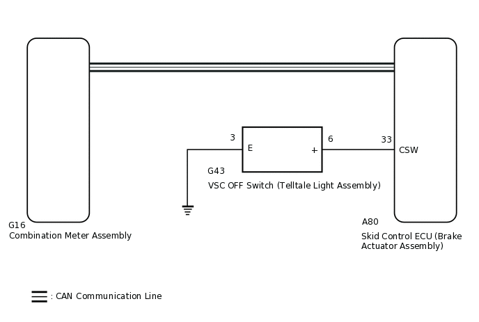
The skid control ECU (brake actuator assembly) is connected to the combination meter assembly via CAN communication.
for Segment Display Type:
Pressing the VSC OFF switch (telltale light assembly) turns off traction control and pressing and holding this switch turns off traction and VSC controls. If traction control turns OFF, the TRC/TRAC OFF indicator light will come on.
If VSC and traction control turns OFF, the TRC/TRAC OFF indicator and VSC OFF indicator light will come on.
The TRC/TRAC OFF indicator light is illuminated when the TRC/TRAC control is prohibited by operating the VSC OFF switch (telltale light assembly).
By pressing the VSC OFF switch (telltale light assembly) for a short time, the TRC/TRAC OFF mode is activated, and the TRC/TRAC control is prohibited, and the TRC/TRAC OFF indicator light in the combination meter is illuminated.
By pressing the VSC OFF switch (telltale light assembly) for 3 seconds or more, the VSC OFF mode is activated, the VSC and TRC/TRAC controls are prohibited, and both the VSC OFF indicator light and the TRC/TRAC OFF indicator light are illuminated.
If there is a malfunction in the SFI system, the TRC/TRAC system will be prohibited and the TRC/TRAC OFF indicator light will turn on (for 2AR-FE, 3ZR-FE).
for TFT Display Type:
Pressing the VSC OFF switch (telltale light assembly) turns off traction control and pressing and holding this switch turns off traction and VSC controls. If traction control turns OFF, TRC OFF is displayed on the multi-information display.
If VSC and traction control turns OFF, TRC OFF is displayed on the multi-information display and the VSC OFF indicator light will come on.
TRC OFF is displayed on the multi-information display when the TRC control is prohibited by operating the VSC OFF switch (telltale light assembly).
By pressing the VSC OFF switch (telltale light assembly) for a short time, the TRC OFF mode is activated, TRC control is prohibited, and TRC OFF is displayed on the multi-information display.
By pressing the VSC OFF switch (telltale light assembly) for 3 seconds or more, the VSC OFF mode is activated, VSC and TRC controls are prohibited, the VSC OFF indicator light illuminates and TRC OFF is displayed on the multi-information display.
If there is a malfunction in the SFI system, the TRC system will be prohibited and the TRC OFF will be displayed on the multi-information display (for 2AR-FE, 3ZR-FE, 3ZR-FAE).
WIRING DIAGRAM
CAUTION / NOTICE / HINT
When replacing the skid control ECU (brake actuator assembly), perform zero point calibration.
PROCEDURE
CHECK ENGINE TYPE
Check the engine type.
Result
Result
Proceed to
2AR-FE
A
3ZR-FAE
3ZR-FE
2AD-FHV
B
2AD-FTV
2WW
B CHECK IF SKID CONTROL ECU CONNECTOR SECURELY CONNECTEDClick here
CHECK SFI SYSTEM
Check if SFI system DTCs are output
for 2AR-FE (w/ Canister Pump Module):Click here
for 2AR-FE (w/o Canister Pump Module):Click here
for 3ZR-FAE:Click here
for 3ZR-FE (for K111, K111F):Click here
for 3ZR-FE (except K111, K111F):Click here
Powertrain > Engine and ECT > Trouble Codes
Result
Proceed to
DTCs are not output
DTCs are output (for 2AR-FE (w/ Canister Pump Module))
DTCs are output (for 2AR-FE (w/o Canister Pump Module))
DTCs are output (for 3ZR-FAE)
DTCs are output (for K111, K111F)
DTCs are output (except K111, K111F)
CHECK IF SKID CONTROL ECU CONNECTOR SECURELY CONNECTED
Check if the skid control ECU (brake actuator assembly) connector is securely connected.
OK
The connector is securely connected.
Result
Proceed to
OK
NG
NG CONNECT CONNECTOR TO ECU CORRECTLY
CHECK CAN COMMUNICATION SYSTEM
Check if CAN communication system DTCs are output.
for LHD with Central Gateway ECU:Click here
for RHD with Central Gateway ECU:Click here
for LHD without Central Gateway ECU:Click here
for RHD without Central Gateway ECU:Click here
Result
Proceed to
DTC is not output
DTC is output (for LHD with Central Gateway ECU)
DTC is output (for RHD with Central Gateway ECU)
DTC is output (for LHD without Central Gateway ECU)
DTC is output (for RHD without Central Gateway ECU)
INSPECT BATTERY
Check the battery voltage.
Standard voltage
11 to 14 V
Result
Proceed to
OK
NG (for 2AD-FHV)
NG (for 2AD-FTV)
NG (for 2AR-FE)
NG (for 3ZR-FAE)
NG (for 3ZR-FE)
NG (for 2WW)
CHECK HARNESS AND CONNECTOR (CSW TERMINAL)
Turn the ignition switch off.
Disconnect the A80 skid control ECU (brake actuator assembly) connector.
-
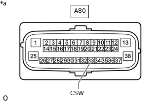
*a
Front view of wire harness connector
(to Skid Control ECU [Brake Actuator Assembly])
Measure the resistance according to the value(s) in the table below.
Standard Resistance
Tester Connection
Switch Condition
Specified Condition
A80-33 (CSW) - Body ground
VSC OFF switch (telltale light assembly) held on
Below 1 Ω
VSC OFF switch (telltale light assembly) off (Not pressed)
10 kΩ or higher
Result
Proceed to
OK
NG
NG INSPECT TELLTALE LIGHT ASSEMBLYClick here
READ VALUE USING GTS (TRC/VSC OFF MODE)
Reconnect the A80 skid control ECU (brake actuator assembly) connector.
Connect the GTS to the DLC3.
Turn the ignition switch to ON.
Turn the GTS on.
Enter the following menus: Chassis / ABS/VSC/TRC / Data List.
According to the display on the GTS, read the Data List.
Chassis > ABS/VSC/TRC > Data List
Tester Display
Measurement Item
Range
Normal Condition
Diagnostic Note
TRC/VSC Off Mode
TRC/TRAC/VSC off mode
Normal, TRC OFF or VSC OFF
Normal: Normal mode
TRC OFF: TRC/TRAC off mode
VSC OFF: VSC off mode
-
Chassis > ABS/VSC/TRC > Data List
Tester Display
TRC/VSC Off Mode
Check that the mode display changes according to the VSC OFF switch (telltale light assembly) operation.
OK
Display changes according to the switch operation.
Result
Proceed to
OK
NG
INSPECT TELLTALE LIGHT ASSEMBLY
Remove the VSC OFF switch (telltale light assembly).
Inspect the VSC OFF switch (telltale light assembly).
Result
Proceed to
OK
NG
CHECK HARNESS AND CONNECTOR (BRAKE ACTUATOR ASSEMBLY - TELLTALE LIGHT ASSEMBLY)
Measure the resistance according to the value(s) in the table below.
Standard Resistance
Tester Connection
Condition
Specified Condition
A80-33 (CSW) - G43-6 (+)
Always
Below 1 Ω
G43-13 (E) - Body ground
Always
Below 1 Ω
A80-33 (CSW) or G43-6 (+) - Body ground
Always
10 kΩ or higher
Result
Proceed to
OK
NG
NG REPAIR OR REPLACE HARNESS OR CONNECTOR