LIGHTING SYSTEM Low Beam Headlight Circuit
| DTC Code | DTC Name |
|---|---|
| Low Beam Headlight Circuit |
DESCRIPTION
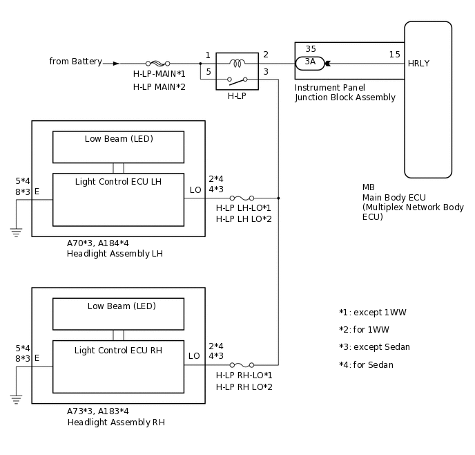
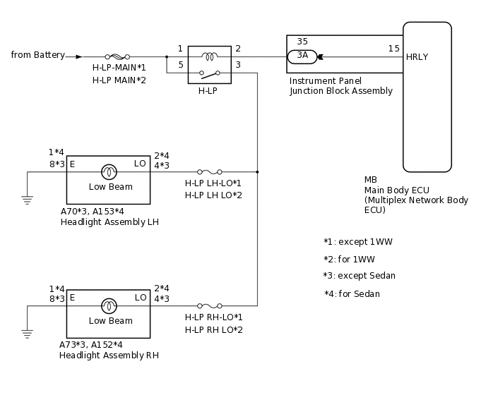
The main body ECU (multiplex network body ECU) controls the low beam headlights.
WIRING DIAGRAM
for LED Headlight
for Halogen Headlight
CAUTION / NOTICE / HINT
Inspect the fuses for circuits related to this system before performing the following procedure.
PROCEDURE
PERFORM ACTIVE TEST USING GTS
Connect the GTS to the DLC3.
Turn the ignition switch to ON.
Turn the GTS on.
Enter the following menus: Body Electrical / Main Body / Active Test.
Perform the Active Test according to the display on the GTS.
Body Electrical > Main Body > Active Test
Tester Display
Measurement Item
Control Range
Diagnostic Note
Headlight Relay
Headlight relay (Low beam headlights)
ON/OFF
-
Body Electrical > Main Body > Active Test
Tester Display
Headlight Relay
OK
Headlight relay operates. (Low beam headlights illuminate.)
Result
Proceed to
OK
NG
INSPECT H-LP RELAY
Remove the H-LP relay from the engine room relay block and junction block assembly.
-
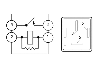
Measure the resistance according to the value(s) in the table below.
Standard Resistance
Tester Connection
Condition
Specified Condition
3 - 5
Voltage not applied between terminals 1 and 2
10 kΩ or higher
3 - 5
Voltage applied between terminals 1 and 2
Below 1 Ω
Result
Proceed to
OK
NG
NG REPLACE H-LP RELAY
CHECK HARNESS AND CONNECTOR (H-LP-MAIN FUSE - H-LP RELAY)
Measure the voltage according to the value(s) in the table below.
Standard Voltage
Tester Connection
Condition
Specified Condition
Relay terminal 1 - Body ground
Always
11 to 14 V
Relay terminal 5 - Body ground
Always
11 to 14 V
Result
Proceed to
OK
NG
NG REPAIR OR REPLACE HARNESS OR CONNECTOR
CHECK HARNESS AND CONNECTOR (H-LP RELAY - HEADLIGHT ASSEMBLY LH AND HEADLIGHT ASSEMBLY RH)
for LED Headlight (except Sedan):
Disconnect the A70 headlight assembly LH connector.
Disconnect the A73 headlight assembly RH connector.
Measure the resistance according to the value(s) in the table below.
Standard Resistance
Tester Connection
Condition
Specified Condition
Relay terminal 3 - A70-4 (LO)
Always
Below 1 Ω
Relay terminal 3 - A73-4 (LO)
Always
Below 1 Ω
Relay terminal 3 - Body ground
Always
10 kΩ or higher
for LED Headlight (for Sedan):
Disconnect the A184 headlight assembly LH connector.
Disconnect the A183 headlight assembly RH connector.
Measure the resistance according to the value(s) in the table below.
Standard Resistance
Tester Connection
Condition
Specified Condition
Relay terminal 3 - A184-2 (LO)
Always
Below 1 Ω
Relay terminal 3 - A183-2 (LO)
Always
Below 1 Ω
Relay terminal 3 - Body ground
Always
10 kΩ or higher
for Halogen Headlight (except Sedan):
Disconnect the A70 headlight assembly LH connector.
Disconnect the A73 headlight assembly RH connector.
Measure the resistance according to the value(s) in the table below.
Standard Resistance
Tester Connection
Condition
Specified Condition
Relay terminal 3 - A70-4 (LO)
Always
Below 1 Ω
Relay terminal 3 - A73-4 (LO)
Always
Below 1 Ω
Relay terminal 3 - Body ground
Always
10 kΩ or higher
for Halogen Headlight (for Sedan):
Disconnect the A153 headlight assembly LH connector.
Disconnect the A152 headlight assembly RH connector.
Measure the resistance according to the value(s) in the table below.
Standard Resistance
Tester Connection
Condition
Specified Condition
Relay terminal 3 - A153-2 (LO)
Always
Below 1 Ω
Relay terminal 3 - A152-2 (LO)
Always
Below 1 Ω
Relay terminal 3 - Body ground
Always
10 kΩ or higher
Result
Proceed to
OK
NG
NG REPAIR OR REPLACE HARNESS OR CONNECTOR
CHECK HARNESS AND CONNECTOR (H-LP RELAY - INSTRUMENT PANEL JUNCTION BLOCK ASSEMBLY)
Disconnect the 3A instrument panel junction block assembly connector.
Measure the resistance according to the value(s) in the table below.
Standard Resistance
Tester Connection
Condition
Specified Condition
Relay terminal 2 - 3A-35
Always
Below 1 Ω
Relay terminal 2 - Body ground
Always
10 kΩ or higher
Result
Proceed to
OK
NG
NG REPAIR OR REPLACE HARNESS OR CONNECTOR
INSPECT INSTRUMENT PANEL JUNCTION BLOCK ASSEMBLY
Remove the instrument panel junction block assembly.
for LHD:Click here
for RHD:Click here
Remove the main body ECU (multiplex network body ECU) from the instrument panel junction block assembly.
Measure the resistance according to the value(s) in the table below.
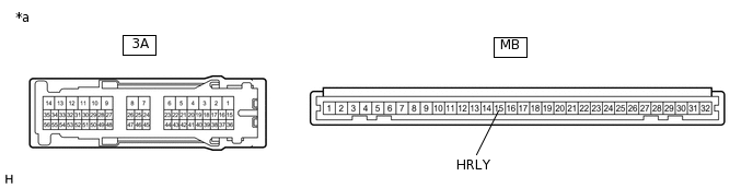
*a
Component without harness connected
(Instrument Panel Junction Block Assembly)
-
-
Standard Resistance
Tester Connection
Condition
Specified Condition
3A-35 - MB-15 (HRLY)
Always
Below 1 Ω
3A-35 - Body ground
Always
10 kΩ or higher
Result
Proceed to
OK
NG