ECD SYSTEM(w/o Glow Plug Controller), Diagnostic DTC:P2032 and P2033
| DTC Code | DTC Name |
|---|---|
| P2032 | Exhaust Gas Temperature Sensor Circuit Low (Bank 1 Sensor 2) |
| P2033 | Exhaust Gas Temperature Sensor Circuit High (Bank 1 Sensor 2) |
DESCRIPTION
Refer to DTC P0545.
DTC No. |
Detection Item |
DTC Detection Condition |
Trouble Area |
MIL |
Memory |
|---|---|---|---|---|---|
P2032 |
Exhaust Gas Temperature Sensor Circuit Low (Bank 1 Sensor 2) |
Exhaust gas temperature sensor B1S2 output voltage is 0.15 V or less. (2 trip detection logic) |
|
Comes on |
DTC stored |
P2033 |
Exhaust Gas Temperature Sensor Circuit High (Bank 1 Sensor 2) |
Exhaust gas temperature sensor B1S2 output voltage is 3.28 V or higher. (2 trip detection logic) |
|
Comes on |
DTC stored |
DTC No. |
DTC Detection Drive Pattern |
|---|---|
P2032 |
Engine idling for 2 seconds or more |
P2033 |
All of the following conditions are met:
|
DTC No. |
Data List |
|---|---|
P2032 |
Exhaust Temperature B1S2 |
P2033 |
When DTC P2032 or P2033 is stored, check the exhaust gas temperature by entering the following menus on the GTS: Powertrain / Engine and ECT / Data List / Exhaust Temperature B1S2.
Temperature Displayed |
Malfunction |
|---|---|
20°C (68°F) |
Open circuit |
900°C (1652°F) |
Short circuit |
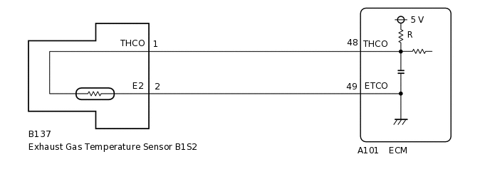
WIRING DIAGRAM
CAUTION / NOTICE / HINT
When the ECM must be replaced, before replacing the ECM, perform the "Learning Values Save" function using the GTS. Then after installing a new ECM, perform all of the initialization and registration procedures for the "Learning Values Write" function by following the instructions shown on the GTS display.
Read freeze frame data using the GTS. Freeze frame data records the engine condition when malfunctions are detected. When troubleshooting, freeze frame data can help determine if the vehicle was moving or stationary, if the engine was warmed up or not, and other data from the time the malfunction occurred.
PROCEDURE
READ VALUE USING GTS (EXHAUST TEMPERATURE B1S2)
Connect the GTS to the DLC3.
Start the engine and warm it up.
Turn the GTS on.
Enter the following menus: Powertrain / Engine and ECT / Data List / Exhaust Temperature B1S2.
Powertrain > Engine and ECT > Data List
Tester Display
Exhaust Temperature B1S2
Read the value.
Standard
Same as the actual exhaust gas temperature (50 to 700°C [122 to 1292°F] while idling after warm-up).
Result
Result
Proceed to
20°C (68°F)
A
900°C (1652°F)
B
Same as the actual exhaust gas temperature (50 to 700°C [122 to 1292°F] while idling after warm-up)
C
Tip:If there is an open circuit, the GTS indicates 20°C (68°F).
If there is a short circuit, the GTS indicates 900°C (1652°F).
B READ VALUE USING GTS (CHECK FOR SHORT IN WIRE HARNESS)Click here
C CONFIRM WHETHER MALFUNCTION HAS BEEN SUCCESSFULLY REPAIREDClick here
READ VALUE USING GTS (CHECK FOR OPEN IN WIRE HARNESS)
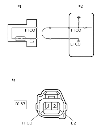
*1
Exhaust Gas Temperature Sensor B1S2
*2
ECM
*a
Front view of wire harness connector
(to Exhaust Gas Temperature Sensor B1S2)
Disconnect the exhaust gas temperature sensor B1S2 connector.
Connect terminals B137-1 (THCO) and B137-2 (E2) of the exhaust gas temperature sensor B1S2 connector on the wire harness side.
Connect the GTS to the DLC3.
Turn the ignition switch to ON and turn the GTS on.
Enter the following menus: Powertrain / Engine and ECT / Data List / Exhaust Temperature B1S2.
Powertrain > Engine and ECT > Data List
Tester Display
Exhaust Temperature B1S2
Read the value.
Standard
900°C (1652°F)
Result
Proceed to
OK
NG
NG CHECK HARNESS AND CONNECTOR (EXHAUST GAS TEMPERATURE SENSOR B1S2 - ECM)Click here
CONFIRM GOOD CONNECTION AT SENSOR. IF OK, REPLACE EXHAUST GAS TEMPERATURE SENSOR B1S2
Replace the exhaust gas temperature sensor B1S2.
Result
Proceed to
NEXT
CONFIRM WHETHER MALFUNCTION HAS BEEN SUCCESSFULLY REPAIRED
Connect the GTS to the DLC3.
Turn the ignition switch to ON and turn the GTS on.
Clear the DTCs.
Powertrain > Engine and ECT > Clear DTCs
Turn the ignition switch off and wait for 30 seconds or more.
Turn the ignition switch to ON and wait for 10 seconds or more.
Start the engine and allow it to idle until the engine coolant temperature is 80°C (176°F) or higher.
Confirm that 11 minutes or more elapsed after engine was started.
Enter the following menus: Powertrain / Engine and ECT / Trouble Codes / Pending.
Confirm that the pending DTC is not output again.
Powertrain > Engine and ECT > Trouble Codes
Result
Proceed to
NEXT
NEXT END
CHECK HARNESS AND CONNECTOR (EXHAUST GAS TEMPERATURE SENSOR B1S2 - ECM)
Disconnect the exhaust gas temperature sensor B1S2 connector.
Disconnect the ECM connector.
Measure the resistance according to the value(s) in the table below.
Standard Resistance
Tester Connection
Condition
Specified Condition
B137-1 (THCO) - A101-48 (THCO)
Always
Below 1 Ω
B137-2 (E2) - A101-49 (ETCO)
Always
Below 1 Ω
Result
Proceed to
OK
NG
NG REPAIR OR REPLACE HARNESS OR CONNECTORClick here
CONFIRM GOOD CONNECTION TO ECM. IF OK, REPLACE ECM
Replace the ECM.
Result
Proceed to
NEXT
NEXT CONFIRM WHETHER MALFUNCTION HAS BEEN SUCCESSFULLY REPAIREDClick here
REPAIR OR REPLACE HARNESS OR CONNECTOR
Result
Proceed to
NEXT
NEXT CONFIRM WHETHER MALFUNCTION HAS BEEN SUCCESSFULLY REPAIREDClick here
READ VALUE USING GTS (CHECK FOR SHORT IN WIRE HARNESS)
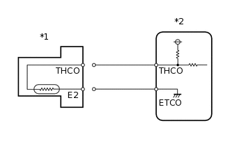
*1
Exhaust Gas Temperature Sensor B1S2
*2
ECM
Disconnect the exhaust gas temperature sensor B1S2 connector.
Connect the GTS to the DLC3.
Turn the ignition switch to ON and turn the GTS on.
Enter the following menus: Powertrain / Engine and ECT / Data List / Exhaust Temperature B1S2.
Powertrain > Engine and ECT > Data List
Tester Display
Exhaust Temperature B1S2
Read the value.
Standard
20°C (68°F)
Result
Proceed to
OK
NG
OK REPLACE EXHAUST GAS TEMPERATURE SENSOR B1S2Click here
CHECK HARNESS AND CONNECTOR (EXHAUST GAS TEMPERATURE SENSOR B1S2 - ECM)
Disconnect the exhaust gas temperature sensor B1S2 connector.
Disconnect the ECM connector.
Measure the resistance according to the value(s) in the table below.
Standard Resistance
Tester Connection
Condition
Specified Condition
B137-1 (THCO) or A101-48 (THCO) - Body ground
Always
10 kΩ or higher
Result
Proceed to
OK
NG
NG REPAIR OR REPLACE HARNESS OR CONNECTORClick here
REPLACE ECM
Replace the ECM.
Result
Proceed to
NEXT
NEXT CONFIRM WHETHER MALFUNCTION HAS BEEN SUCCESSFULLY REPAIREDClick here
REPLACE EXHAUST GAS TEMPERATURE SENSOR B1S2
Replace the exhaust gas temperature sensor B1S2.
Result
Proceed to
NEXT
NEXT CONFIRM WHETHER MALFUNCTION HAS BEEN SUCCESSFULLY REPAIREDClick here