LIGHTING SYSTEM Back Door Courtesy Switch Circuit
| DTC Code | DTC Name |
|---|---|
| Back Door Courtesy Switch Circuit |
DESCRIPTION
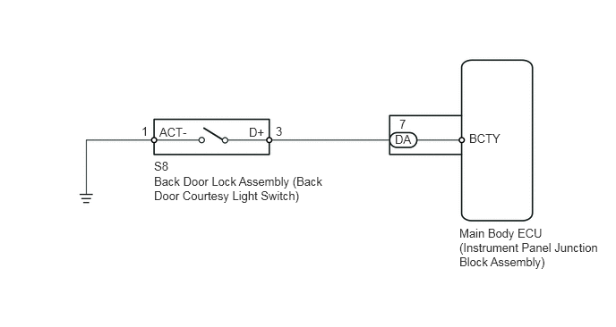
The main body ECU receives a No. 2 room light information signal from the back door courtesy light switch, and illuminates the No. 2 room light.
WIRING DIAGRAM
CAUTION / NOTICE / HINT
Inspect the fuses and bulbs for circuits related to this system before performing the following inspection procedure.
PROCEDURE
READ VALUE USING INTELLIGENT TESTER (BACK DOOR COURTESY SWITCH)
Connect the intelligent tester to the DLC3.
Turn the ignition switch to ON.
Turn the intelligent tester on.
Enter the following menus: Body / Main Body / Data List / Back Door Courtesy Switch.
Use the Data List to check if the back door courtesy light switch is operating properly.
Table 1. Main Body Tester Display
Measurement Item/Range
Normal Condition
Diagnostic Note
Back Door Courtesy Switch
Back door courtesy light switch / ON or OFF
ON: Back door courtesy light switch on
OFF: Back door courtesy light switch off
-
OK
Tester display changes according to opening and closing of back door.
PROCEED TO NEXT SUSPECTED AREA SHOWN IN PROBLEM SYMPTOMS TABLE
INSPECT BACK DOOR LOCK ASSEMBLY (BACK DOOR COURTESY LIGHT SWITCH)
-
Remove the back door lock assembly (back door courtesy light switch) (Click here).
Measure the resistance according to the value(s) in the table below.
Standard Resistance
Tester Connection
Condition
Specified Condition
1 (ACT-) - 3 (D+)
Back door closed
10 kΩ or higher
Back door opened
Below 1 Ω
-
CHECK HARNESS AND CONNECTOR (BACK DOOR LOCK ASSEMBLY - MAIN BODY ECU AND BODY GROUND)
-
Disconnect the S8 back door lock assembly (back door courtesy light switch) connector.
Disconnect the DA main body ECU connector.
Measure the resistance according to the value(s) in the table below.
Standard Resistance
Tester Connection
Condition
Specified Condition
DA-7 (BCTY) - S8-3 (D+)
Always
Below 1 Ω
S8-1 (ACT-) - Body ground
Always
Below 1 Ω
S8-3 (D+) - Body ground
Always
10 kΩ or higher
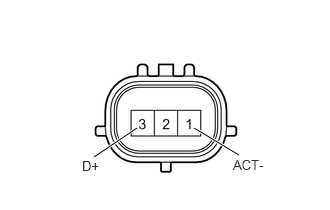
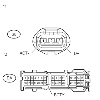
Table 2. Text in Illustration *1
Front view of wire harness connector
(to Back Door Lock Assembly)
*2
Front view of wire harness connector
(to Main Body ECU)
REPLACE MAIN BODY ECU (INSTRUMENT PANEL JUNCTION BLOCK ASSEMBLY)
REPAIR OR REPLACE HARNESS OR CONNECTOR
-