AUTOMATIC TRANSMISSION ASSEMBLY (for 1KD-FTV) INSTALLATION

-
INSTALL TORQUE CONVERTER CLUTCH ASSEMBLY
-
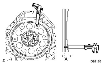
Using vernier calipers, measure dimension A between the transmission and the face of the drive plate.
-
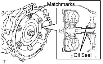
Align the matchmarks on the automatic transmission housing and torque converter clutch assembly and engage the spline of the input shaft and turbine runner.
Note
Install the torque converter clutch assembly onto the input shaft horizontally.
-
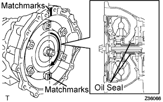
Rotating the converter, fit the spline of the stator shaft with that of the stator.
Tech Tips
Rotate it approximately 180 degrees.
-
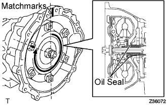
Rotating the converter, align the matchmark on the housing with the one on the converter again and fit the key of the oil pump drive gear into the keyway of the converter.
Note
Do not push the converter excessively when rotating it.
-
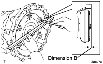
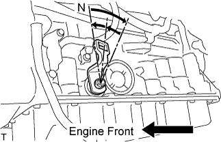
Using calipers and straight edge, measure dimension B shown in the illustration and check that B is greater than A measured in step (a).
Standard Dimension B = A + 1 mm (0.04 in.) or more
-
-
INSTALL BREATHER PLUG HOSE
-
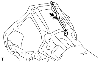
Install the breather plug hose onto the automatic transmission housing with the bolt.
- Torque:
- 7.4 N*m { 76 kgf*cm, 65 in.*lbf }
-
-
INSTALL ENGINE MOUNTING REAR INSULATOR ASSEMBLY
-
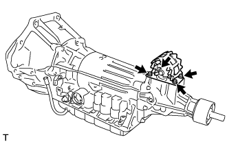
Install the engine mounting rear insulator assembly onto the extension housing sub-assembly with the 4 bolts.
- Torque:
- 18 N*m { 178 kgf*cm, 13 ft.*lbf }
-
-
INSTALL NO. 1 TRANSMISSION CONTROL CABLE BRACKET
-
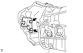
Install the No. 1 transmission control cable bracket onto the automatic transmission housing with the 2 bolts.
- Torque:
- 28 N*m { 286 kgf*cm, 21 ft.*lbf }
-
-
INSTALL AUTOMATIC TRANSMISSION ASSEMBLY
-
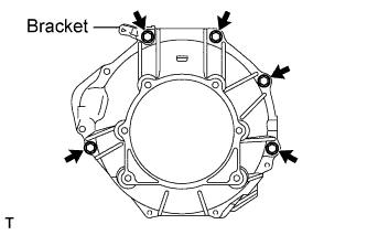
Install the automatic transmission assembly with the 5 bolts.
- Torque:
- 71 N*m { 724 kgf*cm, 52 ft.*lbf }
Tech Tips
Install the bolts so that the bracket is secured as shown in the illustration.
-
-
INSTALL ENGINE MOUNTING REAR INSULATOR ASSEMBLY
-
Install the engine mounting rear insulator assembly with the bolt, the nut and the 2 washers.
- Torque:
- 98 N*m { 999 kgf*cm, 72 ft.*lbf }
Tech Tips
Put a washer under both the bolt head and nut as shown in the illustration.
-
-
INSTALL DRIVE PLATE AND TORQUE CONVERTER CLUTCH SETTING BOLT
-
Turn the crankshaft pulley and install the 6 drive plate and torque converter clutch setting bolts.
- Torque:
- 48 N*m { 490 kgf*cm, 36 ft.*lbf }
Tech Tips
First install the black colored bolt, and then the remaining 5 bolts.
-
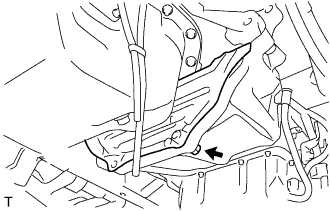
Install the drive plate cover onto the automatic transmission assembly with the bolt.
- Torque:
- 73 N*m { 744 kgf*cm, 54 ft.*lbf }
-
-
INSTALL STIFFENER PLATE RH(ATM)
-
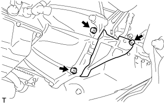
Install the stiffener plate RH with the 3 bolts.
- Torque:
- 71 N*m { 724 kgf*cm, 52 ft.*lbf }
Tech Tips
Install the bolts so that the bracket is secured as shown in the illustration.
-
-
INSTALL NO. 4 CYLINDER BLOCK INSULATOR
-
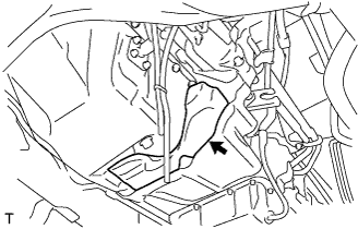
Install the No. 4 cylinder block insulator.
-
-
INSTALL WIRE HARNESS
-
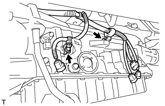
Install the wire harness onto the automatic transmission case sub-assembly with the 2 bolts.
- Torque:
- 5.4 N*m { 55 kgf*cm, 47 in.*lbf }
-
-
INSTALL CONNECTOR
-
w/ Speedometer Sensor:
-
Connect the speedometer sensor connector.
-
-
Connect the temperature sensor connector.
-
Connect the park/neutral switch connector.
-
Connect the No. 2 vehicle speed sensor connector and the transmission wire connector.
-
Connect the overdrive direct clutch speed sensor connector.
-
-
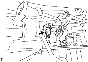
INSTALL OIL COOLER TUBE
-
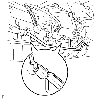
Using a 17 mm union nut wrench, install the 2 oil cooler tubes into each oil cooler tube union.
- Torque:
- 34 N*m { 347 kgf*cm, 25 ft.*lbf }
Note
Use the formula to calculate special torque values for situations where a union nut wrench is combined with a torque wrench Click here.
-
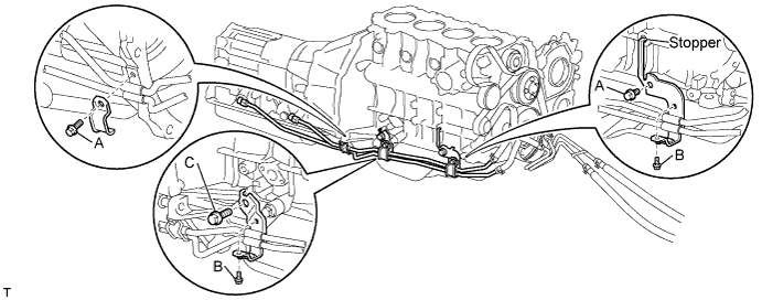
Install the 3 oil cooler tube clamps with the 5 bolts.
- Torque:
- for Bolt A
- 12 N*m { 122 kgf*cm, 9 ft.*lbf }
- for Bolt B
- 8.0 N*m { 82 kgf*cm, 71 in.*lbf }
- for Bolt C
- 71 N*m { 724 kgf*cm, 52 ft.*lbf }
Tech Tips
Insert the stopper into the boss hole on the engine block.
-
-
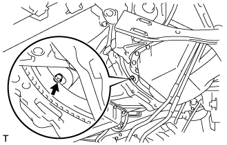
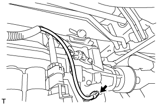
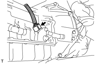
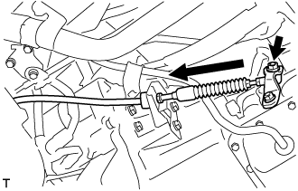
INSTALL TRANSMISSION CONTROL CABLE ASSEMBLY
-
Secure the transmission control cable assembly to the No. 1 transmission control cable bracket with a new clip.
-
Install the transmission control cable assembly onto the control shaft lever with the nut.
- Torque:
- 15 N*m { 150 kgf*cm, 11 ft.*lbf }
-
-
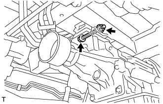
INSTALL TRANSMISSION OIL FILLER TUBE SUB-ASSEMBLY
-
Coat a new O-ring with ATF and install it onto the oil filler tube sub-assembly.
-
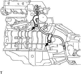
Install the oil filler tube sub-assembly with the 2 bolts.
- Torque:
- 12 N*m { 122 kgf*cm, 9 ft.*lbf }
-
-
INSTALL STARTER ASSEMBLY
-
for 2.2 kW Type:
Install starter assembly Click here.
-
for 2.7 kW Type:
Install starter assembly Click here.
-
-
INSTALL FRONT EXHAUST PIPE ASSEMBLY (w/o DPF)
-
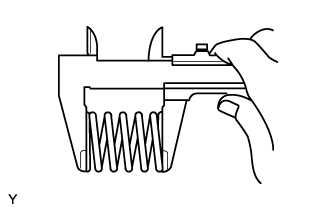
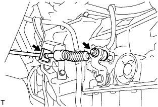
Inspect the compression spring.
-
Using vernier calipers, measure the free length of the compression spring.
Minimum length 40.5 mm (1.594 in.) If the free length is less than the minimum, replace the compression spring.
-
-
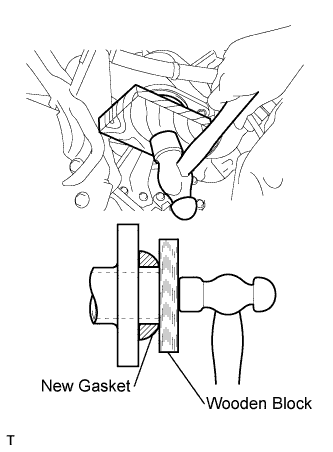
Fully insert a new gasket into the exhaust manifold converter by hand.
-
Using a wooden block, uniformly strike the gasket so that the gasket and exhaust manifold converter are properly fitted.
Note
-
Install the gasket in the correct direction.
-
Do not damage the outer surface of the gasket.
-
Do not reuse the removed gasket.
-
Do not push in the gasket with the front exhaust pipe when connecting it.
-
-
Connect the front exhaust pipe to the No. 4 exhaust pipe support.
-
Install the front exhaust pipe and 2 compression springs with the 2 bolts.
- Torque:
- 43 N*m { 438 kgf*cm, 32 ft.*lbf }
-
-
INSTALL FRONT EXHAUST PIPE ASSEMBLY (w/ DPF)
-
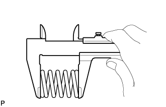
Using a vernier caliper, measure the free length of the compression spring.
Minimum free length 40.5 mm (1.59 in.)
-
If the free length is less than the minimum, replace the compression spring.
-
-
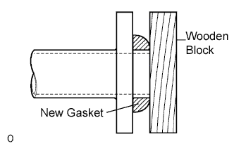
Using a plastic-faced hammer and wooden block, tap on a new gasket until its surface is flush with the front exhaust pipe.
Note
-
Be sure to install the gasket so that it faces the correct direction.
-
Do not reuse the gasket.
-
Do not damage the gasket.
-
When connecting the exhaust pipe, do not push in the gasket with the exhaust pipe.
-
-
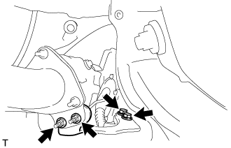
Install a new gasket and the front exhaust pipe to the catalytic converter with pipe with 3 new nuts.
- Torque:
- 63 N*m { 642 kgf*cm, 46 ft.*lbf }
-
Connect the front exhaust pipe to the 2 exhaust pipe supports.
-
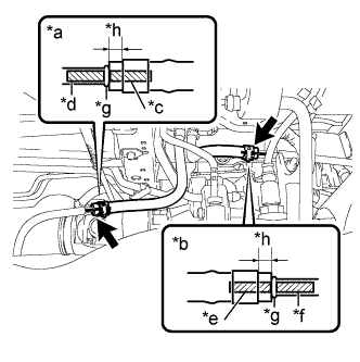
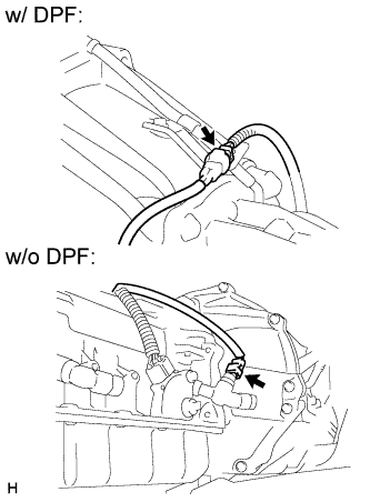
Text in Illustration *a No. 1 Exhaust Pipe Air Hose Side *b No. 7 Exhaust Pipe Air Hose Side *c No. 1 Exhaust Pipe Air Hose Paint Mark (Green) *d front exhaust pipe Assembly Marking (Green) *e No. 7 Exhaust Pipe Air Hose Paint Mark (Pink) *f front exhaust pipe Assembly Marking (Pink) *g Stopper *h 4 to 10 mm Connect the No. 1 exhaust pipe air hose and No. 7 exhaust pipe air hose to the front exhaust pipe with 2 new clips.
Note
-
Align the paint marks of the front exhaust pipe and exhaust pipe air hose and push on the exhaust pipe air hose until it contacts the stopper.
-
Make sure the clip is 4 to 10 mm (0.157 to 0.394 in.) from the end of the exhaust pipe air hose when installing the clip.
-
Make sure that there is no slack in the exhaust pipe air hose, and that it is not twisted or bent.
-
Take care not to damage the inner or outer surface of the exhaust pipe air hose when installing it. If the exhaust pipe air hose is damaged, replace it with a new one.
-
-
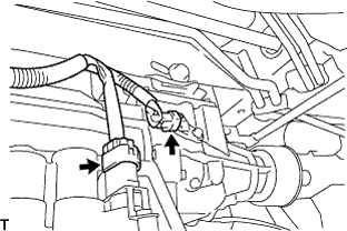
Connect the No. 3 exhaust gas temperature sensor connector and attach the 2 clamps.
-
Connect the No. 2 exhaust gas temperature sensor connector and attach the 2 clamps.
-
Connect the exhaust gas temperature sensor connector and attach the clamp.
-
-
INSTALL PROPELLER SHAFT ASSEMBLY
-
INSTALL TURBINE OUTLET ELBOW STAY (w/ DPF)
-
Install the turbine outlet elbow stay with the 2 bolts and 2 nuts.
- Torque:
- 62 N*m { 632 kgf*cm, 46 ft.*lbf }
-
-
CONNECT CABLE TO NEGATIVE BATTERY TERMINAL
- Torque:
- 5.4 N*m { 55 kgf*cm, 48 in.*lbf }
Note
When disconnecting the cable, some systems need to be initialized after the cable is reconnected Click here.
-
ADD AUTOMATIC TRANSMISSION FLUID
-
INSPECT AUTOMATIC TRANSMISSION FLUID LEVEL
Tech Tips
Drive the vehicle so that the engine and transmission are at normal operating temperature.
Fluid temperature 70 to 80 °C (158 to 176 °F)
-
Park the vehicle on a level surface and set the parking brake.
-
With the engine idling and the brake pedal depressed, move shift the lever into all positions from P to L and return to the P position.
-
Take out the dipstick and wipe it clean.
-
Put it back all the way.
-
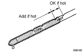
Take it out again and check that the fluid level is within the HOT range.
If the fluid level is below the HOT range, add new fluid and recheck the fluid level. If the fluid level exceeds the HOT range, drain the fluid once, add the proper amount of new fluid and recheck the fluid level.
-
-
INSPECT SHIFT LEVER POSITION
-
When shifting from P position only with ignition switch ON and depress the break pedal.
-
Make sure that the shifting lever moves smoothly and can be moderately operated.
-
When starting engine, make sure that the vehicle moves forward when shifting from N to D position and moves reward when shifting R position.
-
-
ADJUST SHIFT LEVER POSITION
-
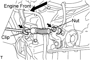
Remove a clip, nut, and disconnect between the control shaft lever to transmission control cable assembly from the control shaft lever and transmission control cable bracket No.1.
-
Turn the control shaft lever until stop to a clockwise direction, return the control shaft lever 2 notches to N position.
-
Set the shift lever to N position while holding the shift lever lightly toward the R position side and install it.
- Torque:
- 15 N*m { 150 kgf*cm, 11 ft.*lbf }
Note
Tighten the nut with it closing up cranky.
-
Inspect the operation condition and work.
-
-
INSPECT FOR FLUID LEAK
-
INSPECT FOR EXHAUST GAS LEAK
-
PERFORM INITIALIZATION