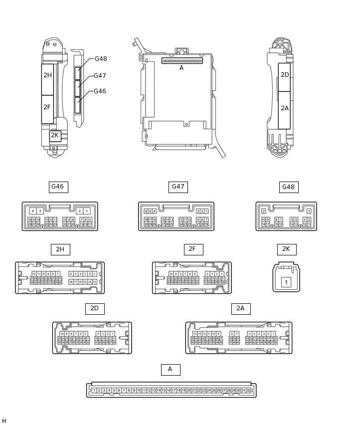
POWER MIRROR CONTROL SYSTEM TERMINALS OF ECU
CHECK OUTER MIRROR CONTROL ECU ASSEMBLY LH
Disconnect the K8 ECU connector.

Measure the voltage and resistance according to the value(s) in the table below.
Tester Connection
Wiring Color
Terminal Description
Condition
Specified Condition
K8-14 (BDR) - Body ground
R - Body ground
Power source
Always
11 to 14 V
K8-6 (CPUB) - Body ground
L - Body ground
Power source
Always
11 to 14 V
K8-5 (SIG) - Body ground
G - Body ground
Power source (IG)
Engine switch off
Below 1 V
Engine switch on (IG)
11 to 14 V
K8-7 (GND) - Body ground
W-B - Body ground
Ground
Always
Below 1 Ω
If the result is not as specified, there may be a malfunction on the wire harness side.
Reconnect the K8 ECU connector.
Measure the voltage according to the value(s) in the table below.
Tester Connection
Wiring Color
Terminal Description
Condition
Specified Condition
K8-1 (MM) - K8-13 (MSWE)
LG - W-B
Seat memory switch SET signal
Seat memory switch SET off
11 to 14 V
Seat memory switch SET on
Below 1 V
K8-2 (M1) - K8-13 (MSWE)
SB - W-B
Seat memory switch M1 signal
Seat memory switch M1 off
11 to 14 V
Seat memory switch M1 on
Below 1 V
K8-3 (M2) - K8-13 (MSWE)
V - W-B
Seat memory switch M2 signal
Seat memory switch M2 off
11 to 14 V
Seat memory switch M2 on
Below 1 V
z3-1 (LMVR) - K8-7 (GND)
V - W-B
Mirror motor drive voltage
LH mirror surface stopped
Below 1 V
LH mirror surface moving downward or left
Below 1 V
LH mirror surface moving upward
11 to 14 V
z3-9 (LMHR) - K8-7 (GND)
BR - W-B
Mirror motor drive voltage
LH mirror surface stopped
Below 1 V
LH mirror surface moving upward or right
Below 1 V
LH mirror surface moving left
11 to 14 V
z3-10 (LM+R) - K8-7 (GND)
R - W-B
Mirror motor drive voltage
LH mirror surface stopped
Below 1 V
LH mirror surface moving upward or left
Below 1 V
LH mirror surface moving downward or right
11 to 14 V
z3-3 (MR+) - Body ground
L - Body ground
Power retract mirror motor drive voltage
Outer rear view mirror LH stopped
Below 1 V
Outer rear view mirror LH being retracted
11 to 14 V
z3-11 (MR-) - Body ground
G - Body ground
Power retract mirror motor drive voltage
Outer rear view mirror LH stopped
Below 1 V
Outer rear view mirror LH returning
11 to 14 V
z3-4 (HTR+) - z3-12 (HTR-)
B - B
Mirror heater relay drive voltage
Rear defogger switch on
11 to 14 V
z3-5 (LVC) - z3-14 (LE1)
R-W - GR
Mirror position sensor power supply
Engine switch on (IG)
4.7 to 5.3 V
z3-6 (VSSR) - z3-14 (LE1)
Y-B - GR
Vertical direction position sensor signal
LH mirror surface moving upward or downward
0.49 to 4.68 V
z3-13 (HSSR) - z3-14 (LE1)
P - GR
Horizontal direction position sensor signal
LH mirror surface moving left or right
0.49 to 4.68 V
z3-7 (EC+) - z3-15 (EC-)
B-G - B-R
EC mirror signal
Electrochromic mirror system is not operating
Below 1 V
Electrochromic mirror system is operating
1.05 to 1.35 V
CHECK OUTER MIRROR CONTROL ECU ASSEMBLY RH
Disconnect the J8 ECU connector.

Measure the voltage according to the value(s) in the table below.
Tester Connection
Wiring Color
Terminal Description
Condition
Specified Condition
J8-6 (CPUB) - Body ground
L - Body ground
Power source
Always
11 to 14 V
J8-14 (BDR) - Body ground
G - Body ground
Power source
Always
11 to 14 V
J8-5 (SIG) - Body ground
G - Body ground
Power source (IG)
Engine switch off
Below 1 V
Engine switch on (IG)
11 to 14 V
J8-7 (GND) - Body ground
W-B - Body ground
Ground
Always
Below 1 Ω
If the result is not as specified, there may be a malfunction on the wire harness side.
Reconnect the J8 ECU connector.
Measure the voltage according to the value(s) in the table below.
Tester Connection
Wiring Color
Terminal Description
Condition
Specified Condition
z2-1 (RMVR) - J8-7 (GND)
V - W-B
Mirror motor drive voltage
RH mirror surface stopped
Below 1 V
RH mirror surface moving downward or left
Below 1 V
RH mirror surface moving upward
11 to 14 V
z2-9 (RMHR) - J8-7 (GND)
BR - W-B
Mirror motor drive voltage
RH mirror surface stopped
Below 1 V
RH mirror surface moving upward or right
Below 1 V
RH mirror surface moving left
11 to 14 V
z2-10 (RM+R) - J8-7 (GND)
R - W-B
Mirror motor drive voltage
RH mirror surface stopped
Below 1 V
RH mirror surface moving upward or left
Below 1 V
RH mirror surface moving downward or right
11 to 14 V
z2-3 (MR+) - Body ground
L - Body ground
Power retract mirror motor drive voltage
Outer rear view mirror RH stopped
Below 1 V
Outer rear view mirror RH being retracted
11 to 14 V
z2-11 (MR-) - Body ground
G - Body ground
Power retract mirror motor drive voltage
Outer rear view mirror RH stopped
Below 1 V
Outer rear view mirror RH returning
11 to 14 V
z2-4 (HTR+) - z2-12 (HTR-)
B - B
Mirror heater relay drive voltage
Mirror heater switch on
11 to 14 V
z2-5 (RVC) - z2-14 (RE1)
R-W - GR
Mirror position sensor power supply
Engine switch on (IG)
4.7 to 5.3 V
z2-6 (VSSR) - z2-14 (RE1)
Y-B - GR
Vertical direction position sensor signal
RH mirror surface moving upward or downward
0.49 to 4.68 V
z2-13 (HSSR) - z2-14 (RE1)
P - GR
Horizontal direction position sensor signal
RH mirror surface moving left or right
0.49 to 4.68 V
z2-7 (EC+) - z2-15 (EC-)
B-G - B-R
EC mirror signal
Electrochromic mirror system is not operating
Below 1 V
Electrochromic mirror system is operating
1.05 to 1.35 V
CHECK DRIVER SIDE JUNCTION BLOCK ASSEMBLY AND MAIN BODY ECU (MULTIPLEX NETWORK BODY ECU)
Remove the main body ECU (Click hereClick here).
Measure the voltage and resistance according to the value(s) in the table below.
Tester Connection
Wiring Color
Terminal Description
Condition
Specified Condition
A-30 (BECU) - Body ground
-
Power source
Always
11 to 14 V
A-32 (IG) - Body ground
-
Power source (IG)
Engine switch off
Below 1 V
Engine switch on (IG)
11 to 14 V
A-11 (GND1) - Body ground
-
Ground
Always
Below 1 Ω
G46-3 (GND2) - Body ground
W-B - Body ground
Ground
Always
Below 1 Ω
If the result is not as specified, there may be a malfunction on the wire harness side.
Install the main body ECU (Click hereClick here).
Measure the voltage according to the value(s) in the table below.
Tester Connection
Wiring Color
Terminal Description
Condition
Specified Condition
G46-13 (MIRB) - G46-15 (MIRE)
P - SB
Mirror adjust switch output
Mirror select switch L or R
Mirror adjust switch off
3.8 to 5 V
Mirror select switch L or R
Mirror adjust switch up
Below 1.7 V
Mirror select switch L or R
Mirror adjust switch right
Below 2.7 V
Mirror select switch L or R
Mirror adjust switch down
Below 3.5 V
Mirror select switch L or R
Mirror adjust switch left
Below 4 V
G46-14 (MIRS) - G46-15 (MIRE)
V - SB
Mirror select switch output
Mirror select switch off
3.8 to 5 V
Mirror select switch L
Below 2 V
Mirror select switch R
Below 1 V
G46-28 (RET) - G46-3 (GND2)
L - W-B
Mirror retract switch output
Mirror retract switch off
Pulse generation (See waveform 1 or 2)
Mirror retract switch on
Below 1 V
-
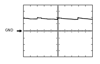
Using an oscilloscope, check waveform 1.
Table 1. Waveform 1 (Reference) Item
Content
Terminal No. (Symbol)
G46-28 (RET) - G46-3 (GND2)
Tool Setting
5 V/DIV., 20 ms/DIV.
Condition
Mirror retract switch off
-
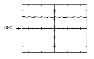
Using an oscilloscope, check waveform 2.
Table 2. Waveform 2 (Reference) Item
Content
Terminal No. (Symbol)
G46-28 (RET) - G46-3 (GND2)
Tool Setting
5 V/DIV., 20 ms/DIV.
Condition
Mirror retract switch off