СТАРТЕР ПРОВЕРКА
-
INSPECT STARTER ASSEMBLY
Note
The following tests must be done within 3 to 5 seconds to prevent the coil from burning out.
-
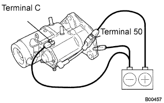
Perform pull-in test.
-
Disconnect the field coil lead wire from terminal C.
-
Connect the battery to the magnetic switch as shown. Check that the clutch pinion gear moves outward.
-
-
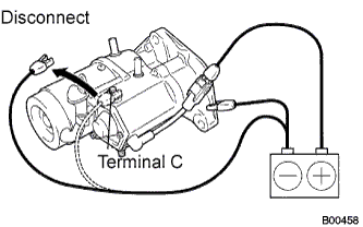
Perform holding test.
-
When the battery is connected as above with the clutch pinion gear out, disconnect the negative (-) lead from terminal C. Check that the pinion gear remains out.
-
-
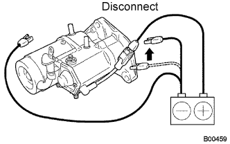
Inspect clutch pinion gear return.
-
Disconnect the negative (-) lead from the starter body. Check that the clutch pinion gear returns inward.
-
-
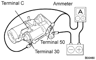
Perform the operation test without load.
-
Connect the field coil lead wire to terminal C.
- Torque:
- 5.9 N*m { 60 kgf*cm, 52 in.*lbf }
-
Grip the starter in a vise.
-
Connect the battery and ammeter to the starter as shown.
-
Check that the ammeter displays the specified current.
Specified current 120 A or less at 11.5 V
-
-
-
INSPECT STARTER ARMATURE ASSEMBLY
-
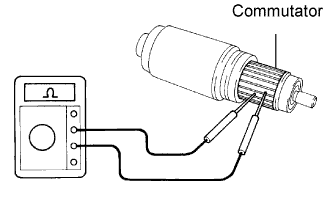
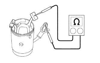
Inspect the commutator for an open circuit.
-
Measure the resistance between the segments of the commutator.
Standard resistance Below 1 Ω
-
If the result is not as specified, replace the armature assembly.
-
-
-
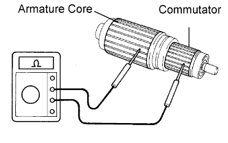
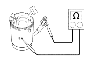
Inspect the commutator for a short circuit.
-
Using an ohmmeter, check that there is no resistance between the commutator and armature core.
Standard resistance 10 kΩ or higher
-
If the result is not as specified, replace the armature assembly.
-
-
-
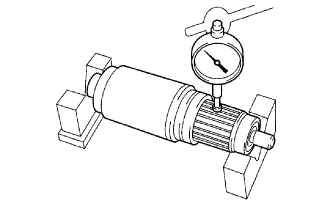
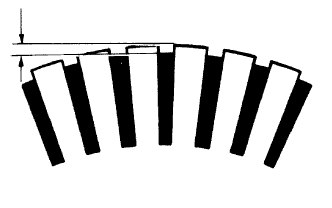
Inspect the commutator circle runout.
-
Place the armature on the V-blocks.
-
Using a dial indicator, measure the circle runout.
Maximum circle runout 0.05 mm (0.0020 in.)
-
If the runout is greater than the maximum, correct it with sandpaper (#400) or replace the armature assembly.
-
-
-
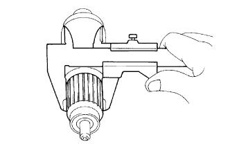
Using a vernier caliper, measure the commutator diameter.
Standard diameter 35.0 mm (1.378 in.) Minimum diameter 34.0 mm (1.339 in.)
-
If the diameter is less than the minimum, replace the armature assembly.
-
-
Measure the undercut depth of the commutator.
Standard depth 0.7 mm (0.028 in.) Minimum depth 0.2 mm (0.008 in.)
-
If the undercut depth is less than the minimum, correct it with a hacksaw blade.
-
-
Inspect the bearings.
-
Check that the bearings rotate smoothly.
If necessary, replace them.
-
-
-
INSPECT STARTER YOKE ASSEMBLY
-
Inspect for an open circuit.
-
Measure the resistance between the terminal C wire and brushes.
Standard resistance Below 1 Ω
-
If the result is not as specified, replace the starter yoke assembly.
-
-
-
Inspect for a short circuit.
-
Measure the resistance between the terminal C wire and starter yoke body.
Standard resistance 10 kΩ or higher -
Measure the resistance between the brushes and starter yoke body.
Standard resistance 10 kΩ or higher
-
If the result is not as specified, replace the starter yoke assembly.
-
-
-
-
INSPECT BRUSH
-
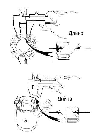
Using a vernier caliper, measure the brush length.
Standard brush length 16.5 mm (0.650 in.) Minimum brush length 9.0 mm (0.354 in.)
-
If the length is less than the minimum, replace the brush holder and starter yoke assembly.
-
-
-
INSPECT STARTER BRUSH HOLDER ASSEMBLY
-
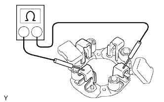
Measure the resistance between the positive and negative brush holders.
Standard resistance 10 kΩ or higher
-
If the result is not as specified, replace the brush holder.
-
-
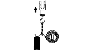
Using a pull scale, measure the brush spring load.
Standard spring load 26.5 to 32.3 N (2.7 to 3.3 kgf, 6.0 to 7.3 lbf) Minimum spring load 17.6 N (1.8 kgf, 4.0 lbf)
-
If the spring load is less than the minimum, replace the brush holder.
-
-
-
INSPECT STARTER CLUTCH SUB-ASSEMBLY
-
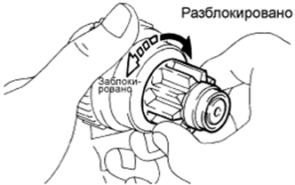
Check that the starter clutch operates.
-
If the starter clutch does not operate, replace it.
-
-
-
INSPECT MAGNET STARTER SWITCH ASSEMBLY
-
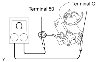
Inspect the pull-in coil.
-
Measure the resistance between terminals 50 and C.
Standard resistance Below 1 Ω
-
If the result is not as specified, replace the magnet starter switch assembly.
-
-
-
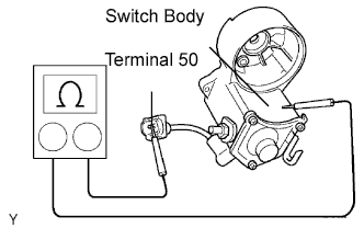
Inspect the holding coil.
-
Measure the resistance between terminal 50 and the switch body.
Standard resistance Below 2 Ω
-
If the result is not as specified, replace the magnet starter switch assembly.
-
-
-