METER / GAUGE SYSTEM Malfunction in Water Temperature Warning Light
DESCRIPTION
In this circuit, the combination meter sub-assembly receives engine coolant temperature signals from the ECM using the CAN communication system. The combination meter sub-assembly displays engine coolant temperature warnings based on the data received from the ECM.
WIRING DIAGRAM
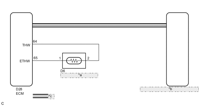
| *a | Engine Coolant Temperature Sensor |
| *b | Combination Meter Sub-assembly (Meter Circuit Plate) |
| *c | CAN Communication Line |
CAUTION / NOTICE / HINT
Tech Tips
-
If there is an open or short in the engine coolant temperature sensor circuit, the ECM stores the DTCs. Troubleshoot the SFI system Click here.
-
If the exhaust heat recirculation system has a malfunction, the water temperature warning light comes on to inform the driver of the malfunction.
PROCEDURE
-
CHECK CAN COMMUNICATION SYSTEM
-
Check if CAN communication DTCs are output Click here.
Result Result Proceed to CAN communication DTCs are not output. A CAN communication DTCs are output. B
B 
GO TO CAN COMMUNICATION SYSTEM Click here
A 
-
-
SYSTEM CHECK
-
Check the Water temperature warning light.
Result Result Proceed to Water temperature warning light does not come on. A Water temperature warning light remains on. B
B 
CHECK FOR DTC Click here
A
-
-
PERFORM ACTIVE TEST USING GTS (INDICAT. LAMP COOLANT HOT)
-
Connect the GTS to the DLC3.
-
Turn the power switch on (IG).
-
Turn the GTS on.
-
Enter the following menus: Body Electrical / Combination Meter / Active Test.
-
Check the operation by referring to the table below.
Combination Meter Tester Display Test Part Control Range Diagnostic Note Indicat. Lamp Coolant Hot Water temperature warning light OFF or ON - OK Water temperature warning light operation is normal.
NG
REPLACE METER CIRCUIT PLATE Click here
OK
-
-
CHECK FOR DTC
-
Check for DTCs (See page for SFI System, Click here for Meter/Gauge System).
Result Result Proceed to DTC is not output. A DTC of SFI system is output. B DTC B1503 is output. C
B
GO TO SFI SYSTEM Click here
C
GO TO METER / GAUGE SYSTEM Click here
A
-
-
READ VALUE USING GTS (COOLANT TEMPERATURE, COOLANT TEMP)
-
Connect the GTS to the DLC3.
-
Turn the power switch on (IG).
-
Turn the GTS on.
-
Enter the following menus:
-
for Combination Meter: Body Electrical / Combination Meter / Data List.
-
for Engine: Powertrain / Engine and ECT / Data List.
-
-
Check the values by referring to the table below.
Combination Meter Tester Display Measurement Item/Range Normal Condition Diagnostic Note Coolant Temperature Engine coolant temperature / 0 to 127.5°C (0 to 261.5°F) After warming up: 75 to 100°C (167 to 212°F) - Engine and ECT Tester Display Measurement Item/Range Normal Condition Stored as Freeze Frame Data Coolant Temp Engine coolant temperature/
Min.: -40°C (-40°F), Max.: 140°C (284°F)
75 to 100°C (167 to 212°F): After warming up Yes Diagnostic Note:
This is the engine coolant temperature.
Tech Tips
-
After warming up the engine, the engine coolant temperature is 75 to 100°C (167 to 212°F).
-
After a long soak, the engine coolant temperature, intake air temperature and ambient air temperature are approximately equal.
-
If the value is -40°C (-40°F) or higher than 135°C (275°F), the sensor circuit may be open or shorted.
-
Check if the engine overheats when the value indicates higher than 135°C (275°F).
Note
Enter inspection mode Click here.
Result Result Proceed to The data list values of the ECUs do not match. A The data list values of the ECUs match. B Tech Tips
When the Data List values of the ECUs do not match, a signal output error of the ECM is suspected.
-
B
GO TO METER / GAUGE SYSTEM Click here
A
-
-
REPLACE METER CIRCUIT PLATE
-
Replace the meter circuit plate with a new or a known good one Click here.
OK The operation of the water temperature warning light returns to normal.
OK
END
NG
REPLACE ECM Click here
-