INTEGRATION RELAY(for Instrument Panel Side) INSTALLATION
CAUTION / NOTICE / HINT
Tech Tips
-
Use the same procedure for RHD and LHD vehicles.
-
The procedure listed below is for LHD vehicles.
PROCEDURE
-
INSTALL NO. 2 SEMICONDUCTOR POWER INTEGRATION ECU (w/ PTC Heater)
-
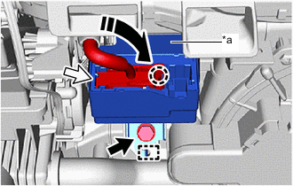
*a Waterproof Film 
Bolt 
Lever Connector 
Rotate in this Direction Align the guide and install the No. 2 semiconductor power integration ECU with the bolt.
Note
-
Make sure the connector terminal is free from oil and grease.
-
Do not subject the No. 2 semiconductor power integration ECU to any impact.
-
Do not use a No. 2 semiconductor power integration ECU that has been dropped.
-
Do not disassemble the No. 2 semiconductor power integration ECU.
- Torque:
- 8.0 N*m { 82 kgf*cm, 71 in.*lbf }
-
-
Attach the claw and connect the lever connector.
Note
-
Make sure the connector terminal is free from oil and grease.
-
Do not subject the No. 2 semiconductor power integration ECU to any impact.
-
Do not use a No. 2 semiconductor power integration ECU that has been dropped.
-
Do not disassemble the No. 2 semiconductor power integration ECU.
-
When connecting the connector, make sure the waterproof film is not pinched.
-
Be sure to connect the lever connector securely.
-
-
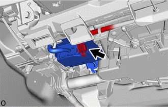
Connect the power source connector.
Note
-
Make sure the connector terminal is free from oil and grease.
-
Do not subject the No. 2 semiconductor power integration ECU to any impact.
-
Do not use a No. 2 semiconductor power integration ECU that has been dropped.
-
Do not disassemble the No. 2 semiconductor power integration ECU.
-
When connecting the connector, make sure the waterproof film is not pinched.
-
-
-
INSTALL SEMICONDUCTOR POWER INTEGRATION ECU (w/o PTC Heater)
Tech Tips
Use the same procedure as for the No. 2 semiconductor power integration ECU.
-
INSTALL NO. 2 INSTRUMENT PANEL UNDER COVER SUB-ASSEMBLY
-
INSTALL INSTRUMENT SIDE PANEL RH
-
CONNECT CABLE TO NEGATIVE BATTERY TERMINAL
-
INSTALL LUGGAGE COMPARTMENT MAT SUB-ASSEMBLY