SFI SYSTEM(w/o Canister Pump Module), Diagnostic DTC:P25A912, P25A914
| DTC Code | DTC Name |
|---|---|
| P25A912 | Piston Cooling Oil Control Circuit Short to Battery |
| P25A914 | Piston Cooling Oil Control Circuit Short to Ground or Open |
DESCRIPTION
Refer to DTC P15E517.
| DTC No. | Detection Item | DTC Detection Condition | Trouble Area | MIL | Memory | Note |
|---|---|---|---|---|---|---|
| P25A912 | Piston Cooling Oil Control Circuit Short to Battery | Monitor current is 0.5 A or higher while the oil pressure switching valve assembly is stopped (1 trip detection logic). |
|
- | DTC stored | SAE: P25AB |
| P25A914 | Piston Cooling Oil Control Circuit Short to Ground or Open | Monitor current is less than 0.5 A while the oil pressure switching valve assembly is operating (1 trip detection logic). |
|
- | DTC stored | SAE: P25AA |
MONITOR DESCRIPTION
When the operation request current and monitor current of the oil pressure switching valve assembly do not match, the ECM judges that a malfunction has occurred in the oil pressure switching valve assembly circuit and stores a DTC.
CONFIRMATION DRIVING PATTERN
-
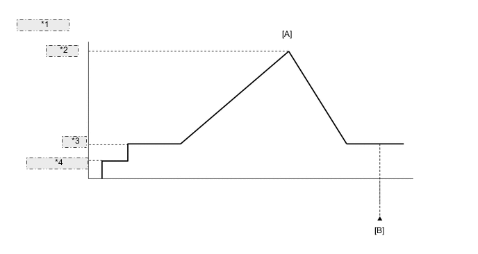
*1 Vehicle Speed *2 4000 rpm *3 Idling *4 Engine Switch on (IG) -
Connect the GTS to the DLC3.
-
Turn the ignition switch to ON.
-
Turn the GTS on.
-
Clear the DTCs (even if no DTCs are stored, perform the clear DTC procedure).
-
Turn the engine switch off and wait for at least 30 seconds.
-
Start the engine.
-
Turn the GTS on.
-
Depress the accelerator pedal, raise the engine speed to approximately 4000 rpm over [A].
-
Enter the following menus: Powertrain / Engine / Trouble Codes [B].
-
Read the pending DTCs.
Tech Tips
-
If a pending DTC is output, the system is malfunctioning.
-
If a pending DTC is not output, perform the following procedure.
-
-
Enter the following menus: Powertrain / Engine / Utility / All Readiness.
-
Input the DTC: P25A912 or P25A914.
-
Check the DTC judgment result.
GTS Display Description NORMAL
-
DTC judgment completed
-
System normal
ABNORMAL
-
DTC judgment completed
-
System abnormal
INCOMPLETE
-
DTC judgment not completed
-
Perform driving pattern after confirming DTC enabling conditions
Tech Tips
-
If the judgment result is NORMAL, the system is normal.
-
If the judgment result is ABNORMAL, the system has a malfunction.
-
WIRING DIAGRAM
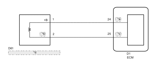
| *a | EOJ+ |
| *b | EOJV |
| *c | EOJ- |
| *d | Oil Pressure Switching Valve Assembly |
CAUTION / NOTICE / HINT
Tech Tips
Read Freeze Frame Data using the GTS. The ECM records vehicle and driving condition information as Freeze Frame Data the moment a DTC is stored. When troubleshooting, Freeze Frame Data can help determine if the vehicle was moving or stationary, if the engine was warmed up or not, if the air fuel ratio was lean or rich, and other data from the time the malfunction occurred.
PROCEDURE
-
INSPECT OIL PRESSURE SWITCHING VALVE ASSEMBLY
-
Inspect the oil pressure switching valve assembly.
Result Proceed to OK NG
NG 
REPLACE OIL PRESSURE SWITCHING VALVE ASSEMBLY Click here
OK 
-
-
CHECK HARNESS AND CONNECTOR (OIL PRESSURE SWITCHING VALVE ASSEMBLY - ECM)
-
Disconnect the oil pressure switching valve assembly connector.
-
Disconnect the ECM connector.
-
Measure the resistance according to the value(s) in the table below.
Standard Resistance Tester Connection Condition Specified Condition D61-1 (+B) - D1-24 (EOJ+) Always Below 1 Ω D61-2 (EOJV) - D1-25 (EOJ-) Always Below 1 Ω D61-1 (+B) or D1-24 (EOJ+) - Body ground and other terminals Always 10 kΩ or higher D61-2 (EOJV) or D1-25 (EOJ-) - Body ground and other terminals Always 10 kΩ or higher Result Proceed to OK NG
OK
REPLACE ECM Click here
NG
REPAIR OR REPLACE HARNESS OR CONNECTOR
-