SMART ENTRY AND START SYSTEM(for Start Function), Diagnostic DTC:B2788
| DTC Code | DTC Name |
|---|---|
| B2788 | IG2 Signal Malfunction |
DESCRIPTION
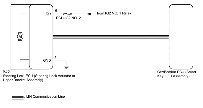
This DTC is stored when the steering lock ECU (steering lock actuator or upper bracket assembly) detects an IG2 power supply malfunction.
Tech Tips
The steering lock ECU (steering lock actuator or upper bracket assembly) is not connected to the CAN communication system. However, the steering lock ECU (steering lock actuator or upper bracket assembly) is connected to the certification ECU (smart key ECU assembly) via LIN communication and communicates with other components via CAN communication through the certification ECU (smart key ECU assembly).
| DTC No. | Detection Item | DTC Detection Condition | Trouble Area | Note |
|---|---|---|---|---|
| B2788 | IG2 Signal Malfunction | Mismatch between the steering lock ECU (steering lock actuator or upper bracket assembly) IG2 input from the LIN communication system and from the direct line. (1-trip detection logic (Only output while a malfunction is present and the engine switch is on (IG).)) |
|
DTC Output Confirmation Operation: No confirmation operation is necessary (monitoring is continuous). |
| Vehicle Condition when Malfunction Detected | Fail-safe Function when Malfunction Detected |
|---|---|
| The steering cannot be locked or unlocked. For this reason, the engine cannot be started. | - |
| DTC No. | Data List and Active Test |
|---|---|
| B2788 | - |
WIRING DIAGRAM
CAUTION / NOTICE / HINT
Note
-
When using the GTS with the engine switch off, connect the GTS to the DLC3 and turn a courtesy light switch on and off at intervals of 1.5 seconds or less until communication between the GTS and the vehicle begins. Then select Model Code "KEY REGIST" under manual mode and enter the following menus: Body Electrical / Entry&Start(CAN). While using the GTS, periodically turn a courtesy light switch on and off at intervals of 1.5 seconds or less to maintain communication between the GTS and the vehicle.
-
The smart entry and start system (for Start Function) uses the LIN communication system and CAN communication system. Inspect the communication function by following How to Proceed with Troubleshooting. Troubleshoot the smart entry and start system (for Start Function) after confirming that the communication systems are functioning properly.
-
Inspect the fuses for circuits related to this system before performing the following procedure.
-
Before replacing the steering lock ECU (steering lock actuator or upper bracket assembly), refer to Service Bulletin.
-
After repair, confirm that no DTCs are output by performing "DTC Output Confirmation Operation".
PROCEDURE
-
CHECK HARNESS AND CONNECTOR (POWER SOURCE)
-
Disconnect the K65 steering lock ECU (steering lock actuator or upper bracket assembly) connector.
-
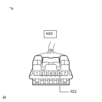
*a Front view of wire harness connector
(to Steering Lock ECU (Steering Lock Actuator or Upper Bracket Assembly))
Measure the voltage according to the value(s) in the table below.
Standard Voltage Tester Connection Condition Specified Condition K65-6 (IG2) - Body ground Engine switch on (IG) 11 to 14 V K65-6 (IG2) - Body ground Engine switch off Below 1 V Result Proceed to OK NG
NG 
REPAIR OR REPLACE HARNESS OR CONNECTOR
OK 
-
-
CHECK HARNESS AND CONNECTOR (GROUND)
-
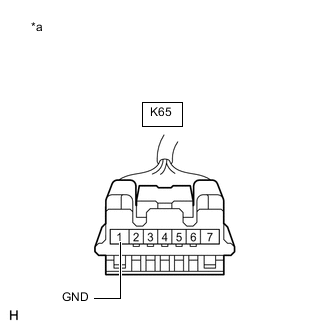
*a Front view of wire harness connector
(to Steering Lock ECU (Steering Lock Actuator or Upper Bracket Assembly))
Measure the resistance according to the value(s) in the table below.
Standard Resistance Tester Connection Condition Specified Condition K65-1 (GND) - Body ground Always Below 1 Ω Result Proceed to OK NG
OK
REPLACE STEERING LOCK ECU (STEERING LOCK ACTUATOR OR UPPER BRACKET ASSEMBLY) for Manual Tilt and Manual Telescopic Steering Column: Click here
REPLACE STEERING LOCK ECU (STEERING LOCK ACTUATOR OR UPPER BRACKET ASSEMBLY) for Power Tilt and Power Telescopic Steering Column: Click hereNG
REPAIR OR REPLACE HARNESS OR CONNECTOR
-