FUEL SUPPLY PUMP REMOVAL
PROCEDURE
PRECAUTION
Note:After the engine has stopped, wait at least 1 minute before releasing the high pressure lines.
When working on the fuel circuit, protect the generator assembly against contamination. Cover the generator assembly with suitable materials. Failure to comply with this procedure may result in a generator assembly malfunction.
-
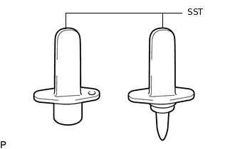
After disconnecting the pressure line, it is absolutely essential to seal the injector assemblies and the common rail assembly with SST.
SST
PZ4TB-04941-79
The position of the fuel supply pump assembly in relation to the valve gear does not affect its function. However, it must be taken into account during removal and installation.
REMOVE FUEL INLET PIPE SUB-ASSEMBLY
SET NO. 1 CYLINDER TO TDC/COMPRESSION
Note:Set the No. 1 cylinder to TDC/compression so that the fuel supply pump assembly can be removed.
REMOVE NO. 1 AND NO. 2 FUEL HOSE PROTECTOR
-
Detach the clamp to disconnect the fuel temperature sensor connector.
Remove the bolt and No. 1 fuel hose protector from the No. 2 fuel hose protector.
-
Remove the No. 2 fuel hose protector from the fuel feed line hose and fuel return line hose.
-
REMOVE FUEL SUPPLY PUMP ASSEMBLY
Note:Do not remove SST A from the injection pump drive gear until all repair work has been completed.
-
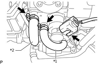
*1
Fuel Feed Line Hose
*2
Fuel Return Line Hose
Disconnect the fuel quantity control valve connector.
Loosen the 2 clamps and disconnect the fuel feed line hose and fuel return line hose from the fuel supply pump assembly.
Remove the 2 clamps from the fuel feed line hose and fuel return line hose.
-
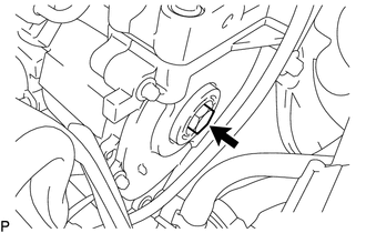
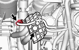
Remove the sealing cap from the timing chain cover plate.
Remove the O-ring from the sealing cap.
-
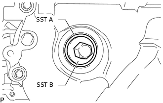
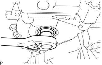
Using SST B, install SST A to position the fuel supply pump assembly. Then remove SST B.
SST
PZ4TB-04967-25
Note:Do not remove SST A from the timing chain cover plate until all repair work has been completed.
-
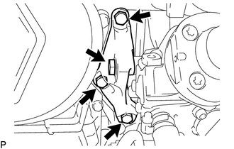
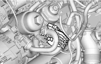
Remove the 4 bolts and fuel supply pump assembly support.
-
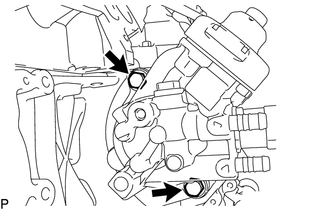
Remove the 2 bolts from the fuel supply pump assembly.
-
Loosen the central bolt connection between the fuel supply pump assembly and injection pump drive gear.
Note:Do not remove SST A from the timing chain cover plate.
The central bolt is supported on SST A until the fuel supply pump assembly is pressed out.
-
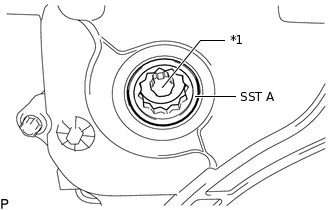
*1
Central Bolt
The central bolt remains inside SST A attached to the injection pump drive gear.
Remove the fuel supply pump assembly from the cylinder block.
Remove the 2 bolts and fuel quantity control valve.
-