BRAKE PEDAL(for RHD) INSTALLATION
PROCEDURE
-
INSTALL BRAKE PEDAL PAD
-
INSTALL BRAKE PEDAL SUPPORT ASSEMBLY
-
Install the nut to the brake pedal support assembly.
-
Install the brake pedal support assembly with the 4 nuts.
- Torque:
- 13 N*m { 130 kgf*cm, 9 ft.*lbf }
-
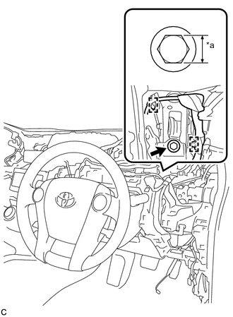
Text in Illustration *a Bolt Width Install the brake pedal support assembly to the instrument panel reinforcement with the bolt.
Bolt Variation Bolt Width Bolt A 14 mm (0.551 in.) Bolt B 12 mm (0.472 in.) - Torque:
- for Bolt A
- 14 N*m { 140 kgf*cm, 10 ft.*lbf }
- for Bolt B
- 24 N*m { 241 kgf*cm, 17 ft.*lbf }
Tech Tips
Two types of bolts each with a different torque specification are used.
-
Engage the 2 clamps.
-
-
INSTALL PUSH ROD PIN
-
Apply lithium soap base glycol grease to the push rod pin and installation hole of the brake pedal support assembly.
-
Install the push rod pin and a new clip to connect the push rod clevis to the brake pedal support assembly.
-
-
ALIGN FRONT WHEELS FACING STRAIGHT AHEAD
-
CONNECT NO. 2 STEERING INTERMEDIATE SHAFT ASSEMBLY
-
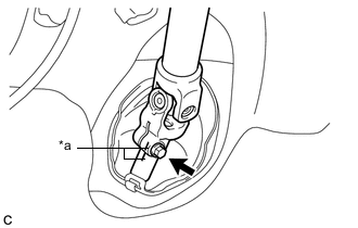
Text in Illustration *a Matchmarks Align matchmarks on the No. 2 steering intermediate shaft assembly and steering intermediate shaft.
-
Connect the No. 2 steering intermediate shaft assembly to the steering intermediate shaft.
-
Install the bolt.
- Torque:
- 35 N*m { 357 kgf*cm, 26 ft.*lbf }
-
-
INSTALL COLUMN HOLE COVER SILENCER SHEET
-
Install the column hole cover silencer sheet with the 2 clips.
-
Turn back the floor carpet.
-
-
INSTALL BRAKE PEDAL RETURN SPRING
-
Install the brake pedal return spring to the brake pedal support assembly and push rod pin.
-
-
INSTALL STOP LIGHT SWITCH MOUNTING ADJUSTER
-
INSTALL STOP LIGHT SWITCH ASSEMBLY
-
INSTALL BRAKE PEDAL STROKE SENSOR ASSEMBLY
-
INSTALL LOWER NO. 1 INSTRUMENT PANEL AIRBAG ASSEMBLY
-
INSTALL LOWER INSTRUMENT PANEL FINISH PANEL SUB-ASSEMBLY
-
INSTALL CONSOLE BOX ASSEMBLY
-
INSTALL POWER STEERING ECU ASSEMBLY
-
INSPECT AND ADJUST BRAKE PEDAL
-
PERFORM INITIALIZATION AND CALIBRATION OF LINEAR SOLENOID VALVE
-
INSTALL NO. 1 INSTRUMENT PANEL UNDER COVER SUB-ASSEMBLY