EXHAUST MANIFOLD INSTALLATION
PROCEDURE
INSTALL AIR FUEL RATIO SENSOR (for Bank 2 Sensor 1)
INSTALL EXHAUST MANIFOLD SUB-ASSEMBLY LH
-
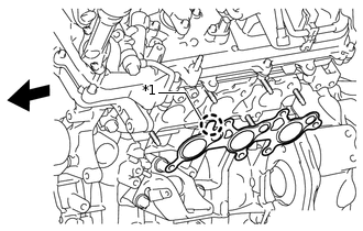
*1
Protrusion

Front
Install a new gasket to the cylinder head.
Note:Be careful of the installation direction.
Temporarily install the exhaust manifold with 6 new nuts.
-
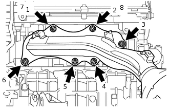
Tighten the 6 nuts in the sequence shown in the illustration.
21 N*m
214 kgf*cm
15 ft.*lbf
Connect the air fuel ratio sensor connector.
-
INSTALL NO. 2 EXHAUST MANIFOLD HEAT INSULATOR
Install the No. 2 exhaust manifold heat insulator with the 3 bolts.
13 N*m
133 kgf*cm
10 ft.*lbf
INSTALL NO. 2 MANIFOLD STAY
Install the No. 2 manifold stay with the 3 bolts.
40 N*m
408 kgf*cm
30 ft.*lbf
INSTALL AIR FUEL RATIO SENSOR (for Bank 1 Sensor 1)
INSTALL EXHAUST MANIFOLD SUB-ASSEMBLY RH
-
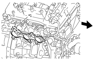
*1
Protrusion
Front
Install a new gasket to the cylinder head.
Note:Be careful of the installation direction.
Temporarily install the exhaust manifold with 6 new nuts.
-
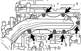
Tighten the 6 nuts in the sequence shown in the illustration.
21 N*m
214 kgf*cm
15 ft.*lbf
Connect the air fuel ratio sensor connector.
-
INSTALL NO. 1 EXHAUST MANIFOLD HEAT INSULATOR
Install the No. 1 exhaust manifold heat insulator with the 3 bolts.
13 N*m
133 kgf*cm
10 ft.*lbf
INSTALL MANIFOLD STAY
Install the manifold stay with the 3 bolts.
40 N*m
408 kgf*cm
30 ft.*lbf
INSTALL FRONT EXHAUST PIPE ASSEMBLY
INSTALL AIR CLEANER CASE SUB-ASSEMBLY
INSTALL AIR CLEANER FILTER ELEMENT SUB-ASSEMBLY
INSTALL AIR CLEANER CAP AND HOSE
INSTALL V-BANK COVER SUB-ASSEMBLY
INSTALL RADIATOR SUPPORT SEAL UPPER
INSPECT FOR EXHAUST GAS LEAK
INSTALL FRONT FENDER APRON SEAL LH
Install the front fender apron seal with the 7 clips.
INSTALL FRONT FENDER APRON SEAL RH
Install the front fender apron seal with the 4 clips.
INSTALL FRONT NO. 1 FENDER APRON TO FRAME SEAL LH
Install the front No. 1 fender apron to frame seal with the 5 clips.
INSTALL FRONT NO. 1 FENDER APRON TO FRAME SEAL RH
Install the front No. 1 fender apron to frame seal with the 5 clips.