ENGINE ON-VEHICLE INSPECTION

CAUTION / NOTICE / HINT
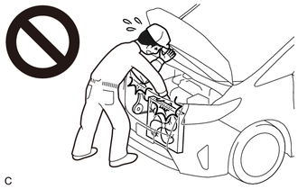
CAUTION:
To prevent injury due to contact with an operating fan and generator V belt or cooling fan, keep your hands and clothing away from the fan and generator V belt and cooling fans when working in the engine compartment with the engine running or the engine switch on (IG).
PROCEDURE
-
INSPECT ENGINE COOLANT
-
INSPECT ENGINE OIL
-
INSPECT BATTERY
-
INSPECT SPARK PLUG
-
INSPECT AIR CLEANER FILTER ELEMENT SUB-ASSEMBLY
-
Remove the air cleaner filter element sub-assembly.
-
Visually check that there is no dirt, blockage, and/or damage to the air cleaner filter element sub-assembly.
Tech Tips
-
If there is any dirt or a blockage in the air cleaner filter element sub-assembly, clean it with compressed air.
-
If any dirt or a blockage remains even after cleaning the air cleaner filter element sub-assembly with compressed air, replace it.
-
-
Install the air cleaner filter element sub-assembly.
-
-
INSPECT FAN AND GENERATOR V BELT
-
INSPECT VALVE LASH ADJUSTER ASSEMBLY
-
Rev up the engine several times. Check that the engine does not emit unusual noises.
If unusual noises occur, warm up the engine and idle it for over 30 minutes. Then perform the inspection above again.
If any defects or problems are found during the inspection above, perform a valve lash adjuster inspection.
-
-
INSPECT IGNITION TIMING
-
Warm up the engine and stop the engine.
Note
A warmed up engine should have an engine coolant temperature of over 80°C (176°F), and an engine oil temperature of 60°C (140°F), and the engine speed should be stabilized.
-
When using the GTS:
-
Connect the GTS to the DLC3.
-
Enter the following menus: Powertrain / Engine / Data List / Ignition Timing Cylinder #1.
Powertrain > Engine > Data ListTester Display Ignition Timing Cylinder #1 -
Monitor Ignition Timing Cylinder #1 of the Data List.
Standard ignition timing 8 to 25° BTDC at idle Note
-
Check the ignition timing with the cooling fans off.
-
Turn off all the electrical systems and the A/C.
-
When checking the ignition timing, the transmission should be in park.
-
-
Enter the following menus: Powertrain / Engine / Active Test / Activate the TC Terminal / ON.
Powertrain > Engine > Active TestActive Test Display Activate the TC Terminal Data List Display Ignition Timing Cylinder #1 -
Monitor Ignition Timing Cylinder #1 of the Data List.
Standard ignition timing 8 to 12° BTDC at idle -
Disconnect the GTS from the DLC3.
-
Check that the ignition timing advances immediately when the engine speed is increased.
-
-
When not using the GTS:
-
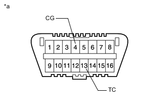
*a Front view of DLC3 Using SST, connect terminals 13 (TC) and 4 (CG) of the DLC3.
- SST
- 09843-18040
Note
-
Confirm the terminal numbers before connecting them. Connecting the wrong terminals can damage the engine.
-
When checking the ignition timing, the transmission should be in neutral.
-
Remove the V-bank cover sub-assembly.
-
Connect the tester probe of a timing light to the wire of the ignition connector for No. 1 cylinder.
Note
Use a timing light which can detect the primary signal.
-
Using a timing light, check the ignition timing.
Standard ignition timing 8 to 12° BTDC at idle -
Remove SST from the DLC3.
-
Check the ignition timing.
Standard ignition timing 8 to 25° BTDC at idle -
Check that the ignition timing advances immediately when the engine speed is increased.
-
Disconnect the timing light from the engine.
-
Install the V-bank cover sub-assembly.
-
-
-
INSPECT ENGINE IDLE SPEED
-
Warm up and stop the engine.
-
When using the GTS:
-
Connect the GTS to the DLC3.
-
Enter the following menus: powertrain / Engine / Data list / Engine Speed.
Powertrain > Engine > Data ListTester Display Engine Speed -
Read the value displayed on the GTS.
Standard idle speed 600 to 800 rpm Note
-
Check the idle speed with the cooling fans off.
-
Turn off all the electrical systems and the A/C.
-
When checking the ignition timing, the transmission should be in park.
-
-
Disconnect the GTS from the DLC3.
-
-
When not using the GTS:
-
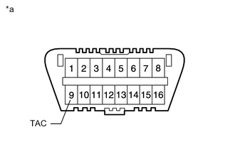
*a Front view of DLC3 Using SST, connect the tachometer probe to terminal 9 (TAC) of the DLC3.
- SST
- 09843-18030
Note
Confirm the terminal numbers before connecting them. Connecting the wrong terminals can damage the engine.
-
Check the idle speed.
Standard idle speed 600 to 800 rpm -
Turn the engine switch off.
-
Disconnect the tachometer from the DLC3.
-
-
-
INSPECT COMPRESSION
Note
Keep the intake manifold and spark plug holes free of foreign matter when measuring the compression pressure.
-
Warm up and stop the engine.
Note
A warmed up engine should have an engine coolant temperature of over 80°C (176°F) and an engine oil temperature of 60°C (140°F), and the engine speed should be stabilized.
-
Connect the GTS to the DLC3.
-
Check for DTCs.
-
w/ Canister Pump Module:
-
w/o Canister Pump Module:
-
-
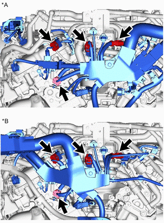
*A for LHD *B for RHD Disconnect the 4 connectors.
-
Remove the 6 spark plugs.
-
Inspect compression pressure.
-
Insert a compression gauge into the spark plug hole.
-
Depress and hold the brake pedal, and turn the engine switch on (IG). Then check the compression pressure.
Standard Compression Pressure 1300 kPa (13.3 kgf/cm2, 189 psi) Minimum Compression Pressure 980 kPa (10.0 kgf/cm2, 142 psi) Pressure Difference between Each Cylinder 200 kPa (2.0 kgf/cm2, 29 psi) or less Note
-
Inspect all cylinders in the same way.
-
Measure the compression pressure as quickly as possible.
-
-
If the cylinder compression pressure is low, pour a small amount of engine oil into the cylinder through the spark plug hole and inspect it again.
Tech Tips
-
If adding oil increases the compression pressure, the piston rings and/or cylinder bore may be worn or damaged.
-
If the compression pressure stays low, a valve may be stuck or seated improperly, or there may be leaks in the cylinder head gasket.
-
-
-
Install the 6 spark plugs.
-
Connect the 4 connectors.
-
Clear the DTCs.
-
w/ Canister Pump Module:
-
w/o Canister Pump Module:
Note
After performing the inspection, clear the DTCs and confirm that DTCs are not stored again or that the normal system code is output if using a check wire.
-
-
-
INSPECT CO/HC
Tech Tips
This is a check for determining whether or not the idle CO / HC complies with regulations.
-
Keep the engine speed at 2500 rpm for approx. 180 seconds.
-
Insert the CO / HC meter testing probe at least 40 cm (1.31 ft.) into the tailpipe during idling.
-
Immediately check CO / HC concentration at idle and/or 2500 rpm.
Tech Tips
-
When performing the 2 mode (2500 rpm and idle) test, follow the measurement order prescribed by the applicable local regulations.
-
If the CO / HC concentration does not comply with regulations, troubleshoot in the order given below.
-
Check the DTCs.
-
w/ Canister Pump Module:
-
w/o Canister Pump Module:
-
-
See the table below for possible causes, then inspect and correct the applicable causes if necessary.
CO HC Symptom Causes Normal High Rough idle
-
Faulty ignitions
-
Incorrect timing
-
Fouled, shorted or improperly gapped plugs
-
Incorrect valve clearance (valve lash adjuster assembly)
-
Leaky intake and exhaust valves
-
Leaky cylinder
Low High Rough idle
(Fluctuating HC reading)
-
Vacuum leaks
-
PCV hose
-
Intake manifold
-
Throttle body with motor assembly
-
Lean mixture causing misfire
High High Rough idle
(Black smoke from exhaust)
-
Restricted air filter
-
Faulty fuel SFI system
-
Faulty fuel pressure
-
Defective engine coolant temperature sensor
-
Faulty ECM
-
Faulty fuel injector assembly
-
Faulty throttle position sensor (built into throttle with motor body assembly)
-
Faulty mass air flow meter
-
-
-