WIPER AND WASHER SYSTEM(w/o Rain Sensor) TERMINALS OF ECU
CHECK WINDSHIELD WIPER SWITCH ASSEMBLY
-
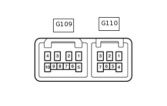
Disconnect the G109 and G110 windshield wiper switch assembly connectors.
Measure the voltage and resistance according to the value(s) in the table below.
Terminal No. (Symbol)
Wiring Color
Terminal Description
Condition
Specified Condition
G109-2 (+B) - Body ground
G - Body ground
Engine switch power supply
Engine switch on (IG)
11 to 14 V
G109-2 (+B) - Body ground
G - Body ground
Engine switch power supply
Engine switch off
Below 1 V
G110-2 (EW) - Body ground
W-B - Body ground
Ground
Always
Below 1 Ω
Reconnect the G109 and G110 windshield wiper switch assembly connectors.
Measure the voltage according to the value(s) in the table below.
Terminal No. (Symbol)
Wiring Color
Terminal Description
Condition
Specified Condition
G110-3 (WF) - Body ground
B - Body ground
Front washer motor output
Windshield wiper switch assembly (windshield washer switch) on
Below 1 V
G110-3 (WF) - Body ground
B - Body ground
Front washer motor output
Windshield wiper switch assembly (windshield washer switch) off
11 to 14 V
G109-3 (+1) - Body ground
B - Body ground
Front wiper motor LO speed signal circuit
Windshield wiper motor assembly in LO operation
11 to 14 V
G109-3 (+1) - Body ground
B - Body ground
Front wiper motor LO speed signal circuit
Windshield wiper motor assembly in not operation
Below 1 V
G109-4 (+2) - Body ground
R - Body ground
Front wiper motor HI speed signal circuit
Windshield wiper motor assembly in HI operation
11 to 14 V
G109-4 (+2) - Body ground
R - Body ground
Front wiper motor HI speed signal circuit
Windshield wiper motor assembly in not operation
Below 1 V
G109-1 (+S) - Body ground
W - Body ground
Front wiper motor operation signal
Windshield wiper motor assembly operations
11 to 14 V
G109-1 (+S) - Body ground
W - Body ground
Front wiper motor operation signal
Windshield wiper motor assembly in not operation
Below 1 V
G110-6 (C1R) - Body ground
B - Body ground
Rear wiper motor LO speed signal circuit
Engine switch on (IG), windshield wiper switch assembly (rear wiper switch) in LO
Below 1 V
G110-6 (C1R) - Body ground
B - Body ground
Rear wiper motor LO speed signal circuit
Engine switch on (IG), windshield wiper switch assembly (rear wiper switch) off
11 to 14 V
G110-7 (+1R) - Body ground
R - Body ground
Rear wiper motor HI speed signal circuit
Engine switch on (IG), windshield wiper switch assembly (rear wiper switch) in HI
Below 1 V
G110-7 (+1R) - Body ground
R - Body ground
Rear wiper motor HI speed signal circuit
Engine switch on (IG), windshield wiper switch assembly (rear wiper switch) off
11 to 14 V
G109-5 (WR) - Body ground
V - Body ground
Rear washer motor output
Windshield wiper switch assembly (rear washer switch) on
Below 1 V
G109-5 (WR) - Body ground
V - Body ground
Rear washer motor output
Windshield wiper switch assembly (rear washer switch) off
11 to 14 V
-
CHECK HEADLIGHT CLEANER CONTROL RELAY (w/ Headlight Cleaner System)
-
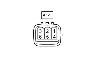
Disconnect the A32 headlight cleaner control relay connector.
Measure the voltage and resistance according to the value(s) in the table below.
Terminal No. (Symbol)
Wiring Color
Terminal Description
Condition
Specified Condition
A32-1 (HDLO) - A32-4 (E)
V - W-B
Low beam headlight signal
Headlight dimmer switch in head
Below 1 V
A32-1 (HDLO) - A32-4 (E)
V - W-B
Low beam headlight signal
Headlight dimmer switch not in head
11 to 14 V
A32-3 (IG) - A32-4 (E)
L - W-B
Engine switch power supply
Engine switch on (IG)
11 to 14 V
A32-3 (IG) - A32-4 (E)
L - W-B
Engine switch power supply
Engine switch off
Below 1 V
A32-4 (E) - Body ground
W-B - Body ground
Body ground
Always
Below 1 Ω
Reconnect the A32 headlight cleaner control relay connector.
Measure the voltage according to the value(s) in the table below.
Tip:The standard normal voltage between each pair of the headlight cleaner control relay terminals is shown in the table below. The appropriate conditions for checking each pair of the terminals are also indicated. The result of checks should be compared with the standard normal voltage for that pair of the terminals, displayed in the Specified Condition column. The illustration above can be used as a reference to identify the headlight cleaner control relay terminal locations.
Terminal No. (Symbol)
Wiring Color
Terminal Description
Condition
Specified Condition
A32-5 (FRWA) - A32-4 (E)
B - W-B
Windshield washer switch operation signal
Engine switch on (IG), windshield wiper switch assembly (windshield washer switch) on
Below 1 V
A32-5 (FRWA) - A32-4 (E)
B - W-B
Windshield washer switch operation signal
Engine switch on (IG), windshield wiper switch assembly (windshield washer switch) off
11 to 14 V
-
CHECK DRIVER SIDE JUNCTION BLOCK ASSEMBLY AND MAIN BODY ECU (MULTIPLEX NETWORK BODY ECU)
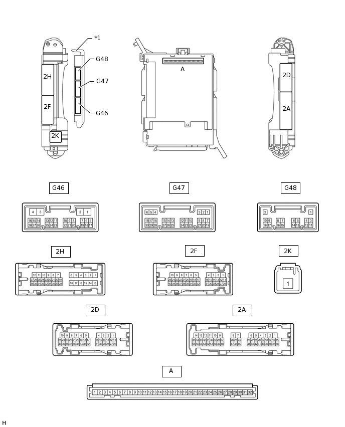
*1
Main Body ECU (Multiplex Network Body ECU)
-
-
Remove the main body ECU (multiplex network body ECU).
Measure the voltage and resistance according to the value(s) in the table below.
Tip:Measure the values on the wire harness side with the connector disconnected.
Terminal No. (Symbol)
Wiring Color
Terminal Description
Condition
Specified Condition
A-30 (BECU) - Body ground
-
Battery power supply
Always
11 to 14 V
A-31 (ALTB) - Body ground
-
Battery power supply
Always
11 to 14 V
A-32 (IG) - Body ground
-
Engine switch power supply
Engine switch on (IG)
11 to 14 V
A-32 (IG) - Body ground
-
Engine switch power supply
Engine switch off
Below 1 V
A-29 (ACC) - Body ground
-
ACC power supply
Engine switch on (ACC)
11 to 14 V
A-29 (ACC) - Body ground
-
ACC power supply
Engine switch off
Below 1 V
A-11 (GND1) - Body ground
-
Ground
Always
Below 1 Ω
G46-3 (GND2) - Body ground
W-B - Body ground
Ground
Always
Below 1 Ω
Install the main body ECU (multiplex network body ECU).
Measure the voltage according to the value(s) in the table below.
Terminal No. (Symbol)
Wiring Color
Terminal Description
Condition
Specified Condition
2F-40 (HRLY) - 2D-4 (GND1)
GR - W-B
H-LP LO relay drive output
Headlight dimmer switch in head
Below 1 V
2F-40 (HRLY) - 2D-4 (GND1)
GR - W-B
H-LP LO relay drive output
Headlight dimmer switch not in head
11 to 14 V
G46-16 (HDLO) - G46-3 (GND2)
V - W-B
Low beam headlight signal
Headlight dimmer switch in head
Below 1 V
G46-16 (HDLO) - G46-3 (GND2)
V - W-B
Low beam headlight signal
Headlight dimmer switch not in head
11 to 14 V
G47-19 (BCTY) - G46-3 (GND2)
G - W-B
Back door courtesy light switch input
Back door open
Below 1 V
G47-19 (BCTY) - G46-3 (GND2)
G - W-B
Back door courtesy light switch input
Back door closed
Pulse generation (See waveform 1 or 2)
G47-1 (GCTY) - G46-3 (GND2)
V - W-B
Glass hatch courtesy switch input
Glass hatch open
Below 1 V
G47-1 (GCTY) - G46-3 (GND2)
V - W-B
Glass hatch courtesy switch input
Engine switch off, all doors closed and glass hatch closed
Pulse generation (See waveform 3 or 4)
G46-20 (PWMR) - G46-3 (GND2)
B - W-B
Rear wiper power supply input
Engine switch on (IG), glass hatch open
Below 1 V
G46-20 (PWMR) - G46-3 (GND2)
B - W-B
Rear wiper power supply input
Engine switch on (IG), glass hatch closed
11 to 14 V
-
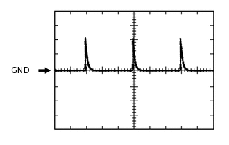
Using an oscilloscope, check waveform 1.
Table 1. Waveform 1 (Reference) Item
Content
Terminal No. (Symbol)
G47-19 (BCTY) - G46-3 (GND2)
Tool Setting
5 V/DIV., 20 ms/DIV.
Condition
Back door closed
-
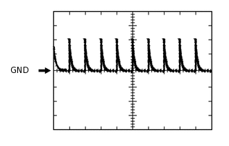
Using an oscilloscope, check waveform 2.
Table 2. Waveform 2 (Reference) Item
Content
Terminal No. (Symbol)
G47-19 (BCTY) - G46-3 (GND2)
Tool Setting
5 V/DIV., 20 ms/DIV.
Condition
Back door closed
-
Using an oscilloscope, check waveform 3.
Table 3. Waveform 3 (Reference) Item
Content
Terminal No. (Symbol)
G47-1 (GCTY) - G46-3 (GND2)
Tool Setting
5 V/DIV., 20 ms/DIV.
Condition
Engine switch off, all doors closed and glass hatch closed
-
Using an oscilloscope, check waveform 4.
Table 4. Waveform 4 (Reference) Item
Content
Terminal No. (Symbol)
G47-1 (GCTY) - G46-3 (GND2)
Tool Setting
5 V/DIV., 20 ms/DIV.
Condition
Engine switch off, all doors closed and glass hatch closed