AUDIO AND VISUAL SYSTEM(for 8 Speakers) TERMINALS OF ECU
-
RADIO RECEIVER ASSEMBLY
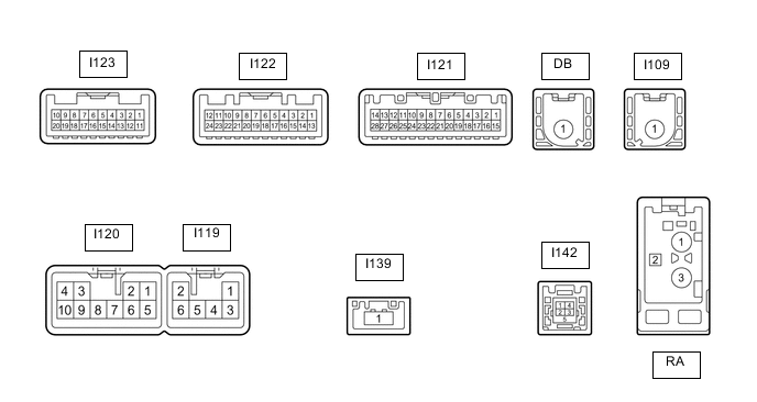
Terminal No. (Symbol) Wiring Color Terminal Description Condition Specification I122-3 (CNH1) R Local bus communication signal - - I122-4 (CNL1) W Local bus communication signal - - I122-7 (TX3+)*6 R AVC-LAN communication signal - - I122-8 (TX3-)*6 L AVC-LAN communication signal - - I122-18 (TX2+) R AVC-LAN communication signal - - I122-19 (TX2-) L AVC-LAN communication signal - - I121-1 (IG) - I120-7 (GND1) P - W-B Power source (IG) Engine switch off Below 1 V Engine switch on (IG) 11 to 14 V I121-4 (MACC) - I120-7 (GND1) B - W-B Telephone microphone assembly power supply Engine switch off Below 1 V Engine switch on (ACC) 4 to 6 V I121-5 (MIN+) - I120-7 (GND1) W - W-B Telephone microphone assembly voice signal See "Check Microphone" in Operation Check
- I121-6 (SNS2) - I120-7 (GND1) P - W-B Telephone microphone assembly connection detection signal Always Below 1 V I121-7 (TX1+)*1 R AVC-LAN communication signal - - I121-8 (TX1-)*1 L AVC-LAN communication signal - - I121-9 (CANH) B*3
Y*4
CAN communication signal - - I121-10 (CANL) W CAN communication signal - - I121-11 (AGND) - Body ground Shielded - Body ground Shielded ground Always Below 1 Ω I121-12 (SG) - I120-7 (GND1) Shielded - W-B Shielded ground Always Below 1 Ω I121-13 (VV+) - I120-7 (GND1) G - W-B Video signal External device playing (When stereo jack used) A waveform synchronized with video signals is output I121-14 (VV-) - I120-7 (GND1) R - W-B Video signal External device playing (When stereo jack used) A waveform synchronized with video signals is output I121-16 (MUT1) - I120-7 (GND1)*1 P - W-B Mute signal Engine switch on (ACC), audio system playing 2.0 V or higher Audio system changing modes Below 1 V I121-17 (SPD) - I120-7 (GND1) W - W-B Vehicle speed signal See "Check Vehicle Signal" in Operation Check
- I121-18 (SGND) - Body ground Shielded - Body ground Shielded ground Always Below 1 Ω I121-19 (MIN-) - I120-7 (GND1) R - W-B Telephone microphone assembly voice signal See "Check Microphone" in Operation Check
- I121-21 (SW1) - I121-23 (SWG) P - W-B Steering pad switch signal No switch pushed 2.97 to 3.56 V Seek+ switch pushed 0.27 to 0.35 V Seek- switch pushed 0.86 to 1.03 V Volume+ switch pushed 1.51 to 1.79 V Volume- switch pushed 2.22 to 2.66 V I121-22 (SW2) - I121-23 (SWG) R - W-B Steering pad switch signal No switch pushed 2.97 to 3.56 V MODE switch pushed 0.27 to 0.35 V On hook switch pushed 0.86 to 1.03 V Off hook switch pushed 1.51 to 1.79 V Voice switch pushed 2.22 to 2.66 V I121-23 (SWG) - I120-7 (GND1) W-B - W-B Steering pad switch ground Always Below 1 V I121-25 (ADPG) - I120-7 (GND1) L - W-B External device connection detection signal External device connected Below 1 V External device not connected 2.1 to 3 V I121-26 (VAR+) - I121-27 (VA-) W - R Sound signal (Right) External device playing (When stereo jack used) A waveform synchronized with sound signals is output I121-27 (VA-) - I120-7 (GND1) R - W-B Ground Always Below 1 V I121-28 (VAL+) - I121-27 (VA-) B - R Sound signal (Left) External device playing (When stereo jack used) A waveform synchronized with sound signals is output I123-1 (VMTF) - I120-7 (GND1) V - W-B Visual mute signal Engine switch on (ACC), screen display changes 2 V or higher
→ Below 1 V
→ 2 V or higher
I123-11 (TX4+) B AVC-LAN communication signal - - I123-12 (TX4-) P AVC-LAN communication signal - - I120-1 (FR+) - I120-7 (GND1) G - W-B*1
R - W-B*2
Sound signal (Right) Audio system playing A waveform synchronized with sound signals is output I120-2 (FL+) - I120-7 (GND1) W - W-B Sound signal (Left) Audio system playing A waveform synchronized with sound signals is output I120-3 (ACC1) - I120-7 (GND1) GR - W-B Power source (ACC) Engine switch off Below 1 V Engine switch on (ACC) 10.5 to 16 V*7
11 to 14 V*8
I120-4 (+B1) - I120-7 (GND1) B - W-B*7
P - W-B*8
Power source (+B) Always 10.5 to 16 V*7
11 to 14 V*8
I120-5 (FR-) - I120-7 (GND1) B - W-B*1
P - W-B*2
Sound signal (Right) Audio system playing A waveform synchronized with sound signals is output I120-6 (FL-) - I120-7 (GND1) R - W-B*1
B - W-B*2
Sound signal (Left) Audio system playing A waveform synchronized with sound signals is output I120-7 (GND1) - Body ground W-B - Body ground Ground Always Below 1 V I120-10 (ILL+) - I120-7 (GND1) Y - W-B Illumination signal Light control switch off Below 1 V Light control switch in tail or head position 11 to 14 V I119-1 (RR+) - I120-7 (GND1)*2 R - W-B Voice signal Voice guidance sounding A waveform synchronized with voice signals is output I119-2 (RL+) - I120-7 (GND1) G - W-B*1
R - W-B*2
Voice signal Voice guidance sounding A waveform synchronized with voice signals is output I119-3 (RR-) - I120-7 (GND1)*2 W - W-B Voice signal Voice guidance sounding A waveform synchronized with voice signals is output I119-5 (ILL-) - I120-7 (GND1) V - W-B Illumination signal Light control switch in tail or head position Pulse generation I119-6 (RL-) - I120-7 (GND1) R - W-B*1
W - W-B*2
Voice signal Voice guidance sounding A waveform synchronized with voice signals is output I142-1 (USV1) # Power source - - I142-2 (US1-) # Data signal - - I142-3 (US1+) # Data signal - - I142-4 (UGD1) # Ground - - I142-5 (USG1) Shielded Shielded ground - - I139-1 (GVIF) B Video signal (Digital) - - I109-1 (GPS)*5 B GPS antenna signal - - #: There is no wire color information
*1: w/ Stereo Component Amplifier
*2: w/o Stereo Component Amplifier
*3: for LHD
*4: for RHD
*5: w/ Navigation Antenna
*6: w/ Panoramic View Monitor System
*7: w/ Stop and Start System
*8: w/o Stop and Start System
-
STEREO COMPONENT AMPLIFIER ASSEMBLY (w/ Stereo Component Amplifier)
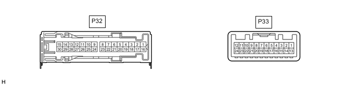
Terminal No. (Symbol) Wiring Color Terminal Description Condition Specification P32-1 (+B) - P32-3 (GND) R - W-B Power source (+B) Always 10.5 to 16 V*1
11 to 14 V*2
P32-3 (GND) - Body ground W-B - Body ground Ground Always Below 1 Ω P32-4 (WFL+) - P32-3 (GND) B - W-B Sound signal (Front Left) Audio system playing A waveform synchronized with sound signals is output P32-5 (WFR+) - P32-3 (GND) W - W-B Sound signal (Front Right) Audio system playing A waveform synchronized with sound signals is output P32-12 (FL+) - P32-3 (GND) P - W-B Sound signal (Front Left) Audio system playing A waveform synchronized with sound signals is output P32-13 (FR+) - P32-3 (GND) P - W-B Sound signal (Front Right) Audio system playing A waveform synchronized with sound signals is output P32-14 (RL+) - P32-3 (GND) R - W-B Sound signal (Rear Left) Audio system playing A waveform synchronized with sound signals is output P32-15 (RR+) - P32-3 (GND) R - W-B Sound signal (Rear Right) Audio system playing A waveform synchronized with sound signals is output P32-16 (+B2) - P32-3 (GND) B - W-B Power source (+B) Always 10.5 to 16 V*1
11 to 14 V*2
P32-18 (GND2) - Body ground W-B - Body ground Ground Always Below 1 Ω P32-19 (WFL-) - P32-3 (GND) Y - W-B Sound signal (Front Left) Audio system playing A waveform synchronized with sound signals is output P32-20 (WFR-) - P32-3 (GND) R - W-B Sound signal (Front Right) Audio system playing A waveform synchronized with sound signals is output P32-27 (FL-) - P32-3 (GND) V - W-B Sound signal (Front Left) Audio system playing A waveform synchronized with sound signals is output P32-28 (FR-) - P32-3 (GND) R - W-B Sound signal (Front Right) Audio system playing A waveform synchronized with sound signals is output P32-29 (RL-) - P32-3 (GND) W - W-B Sound signal (Rear Left) Audio system playing A waveform synchronized with sound signals is output P32-30 (RR-) - P32-3 (GND) W - W-B Sound signal (Rear Right) Audio system playing A waveform synchronized with sound signals is output P33-1 (MUTE) - P32-3 (GND) P - W-B Mute signal Engine switch on (ACC), audio system playing 2.0 V or higher Audio system changing modes Below 1 V P33-2 (L-) - P32-3 (GND) R - W-B Sound signal (Left) Audio system playing A waveform synchronized with sound signals is output P33-3 (L+) - P32-3 (GND) W - W-B Sound signal (Left) Audio system playing A waveform synchronized with sound signals is output P33-4 (R-) - P32-3 (GND) B - W-B Sound signal (Right) Audio system playing A waveform synchronized with sound signals is output P33-5 (R+) - P32-3 (GND) G - W-B Sound signal (Right) Audio system playing A waveform synchronized with sound signals is output P33-6 (SLD) - Body ground Shielded - Body ground Shielded ground Always Below 1 Ω P33-7 (TX-) L AVC-LAN communication signal - - P33-8 (TX+) R AVC-LAN communication signal - - P33-11 (SPD) - P32-3 (GND) V - W-B Vehicle speed signal Engine switch on (IG), wheel being rotated Pulse generation P33-12 (ACC) - P32-3 (GND) P - W-B Power source (ACC) Engine switch off Below 1 V Engine switch on (ACC) 10.5 to 16 V*1
11 to 14 V*2
P33-14 (II1-) - P32-3 (GND) R - W-B Voice signal Voice guidance sounding A waveform synchronized with voice signals is output P33-15 (II1+) - P32-3 (GND) G - W-B Voice signal Voice guidance sounding A waveform synchronized with voice signals is output P33-18 (SLD1) - Body ground Shielded - Body ground Shielded ground Always Below 1 Ω *1: w/ Stop and Start System
*2: w/o Stop and Start System
-
MULTI-DISPLAY ASSEMBLY
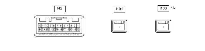
*A w/ Panoramic View Monitor System - - Terminal No. (Symbol) Wiring Color Terminal Description Condition Specification I42-2 (ILL) - I42-13 (GND1) LG - W-B Illumination signal Light control switch off Below 1 V Light control switch in tail or head position 11 to 14 V I42-6 (TX1+)*1 B AVC-LAN communication signal - - I42-7 (TX+) B AVC-LAN communication signal - - I42-11 (VMTI) - I42-13 (GND1) V - W-B Visual mute signal Engine switch on (ACC), screen display changes 2 V or higher
→ Below 1 V
→ 2 V or higher
I42-12 (B) - I42-13 (GND1) R - W-B*3
BE - W-B*4
Power source (+B) Always 10.5 to 16 V*3
11 to 14 V*4
I42-13 (GND1) - Body ground W-B - Body ground Ground Always Below 1 V I42-18 (TX1-)*1 P AVC-LAN communication signal - - I42-19 (TX-) P AVC-LAN communication signal - - I42-24 (ACC) - I42-13 (GND1) V - W-B*3
W - W-B*4
Power source (ACC) Engine switch off Below 1 V Engine switch on (ACC) 10.5 to 16 V*3
11 to 14 V*4
I101-1 (GVIF) B Video signal (Digital) - - I108-1 (GVIF)*2 B Video signal (Digital) - - *1: w/ Headup Display
*2: w/ Panoramic View Monitor System
*3: w/ Stop and Start System
*4: w/o Stop and Start System
-
REMOTE OPERATION CONTROLLER ASSEMBLY

Terminal No. (Symbol) Wiring Color Terminal Description Condition Specification I132-1 (ILL+) - I132-4 (GND) SB - LA Illumination signal Engine switch on (IG), light control switch off Below 1 V Engine switch on (IG), light control switch in tail or head position 11 to 14 V I132-4 (GND) - Body ground LA - Body ground Ground Always Below 1 V I132-8 (ILL-) - I132-4 (GND) L - LA Illumination signal Light control switch off Below 1 V Light control switch in tail or head position Pulse generation I132-10 (TX+) R AVC-LAN communication signal - - I132-11 (TX-) L AVC-LAN communication signal - - I132-14 (ACC) - I132-4 (GND) W - LA*1
LG - LA*2
Power source (ACC) Engine switch off Below 1 V Engine switch on (ACC) 10.5 to 16 V*1
11 to 14 V*2
*1: w/ Stop and Start System
*2: w/o Stop and Start System