EXHAUST MANIFOLD W/ TURBOCHARGER INSTALLATION
PROCEDURE
INSTALL EXHAUST MANIFOLD
Install 2 new gaskets to the cylinder head sub-assembly.
Temporarily install the exhaust manifold with the 8 nuts.
Tighten the 8 nuts of the exhaust manifold.
11 N*m
112 kgf*cm
8 ft.*lbf
Tighten the 8 nuts again.
13 N*m
133 kgf*cm
10 ft.*lbf
INSTALL EGR COOLER ASSEMBLY WITH EGR VALVE ASSEMBLY
INSTALL NO. 1 EXHAUST MANIFOLD HEAT INSULATOR
CONNECT FUEL FEED PIPE SUB-ASSEMBLY
CONNECT NO. 1 AIR TUBE ASSEMBLY
Connect the No. 1 air tube assembly to the manual transaxle assembly with the 2 bolts.
20 N*m
204 kgf*cm
15 ft.*lbf
Connect the outlet heater water hose to the No. 2 radiator pipe, and slide the clamp to secure the hose.
Connect the water hose sub-assembly to the No. 1 radiator pipe, and slide the clamp to secure the hose.
Attach the clamp and connect the water hose sub-assembly to the compressor outlet elbow.
Connect the water by-pass hose assembly to the No. 2 radiator pipe, and slide the clamp to secure the hose.
Connect the radiator hose sub-assembly to the No. 1 radiator pipe, and slide the clamp to secure the hose.
INSTALL NO. 4 WATER BY-PASS HOSE
Install the No. 4 water by-pass hose to the No. 2 radiator pipe, and slide the clamp to secure the hose.
-
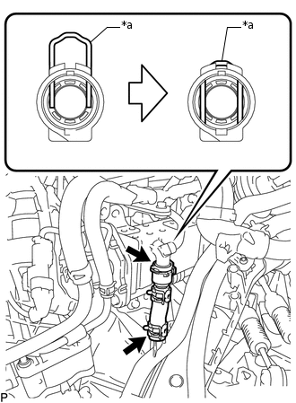
*a
Retainer
Connect the No. 4 water by-pass hose to the EGR cooler assembly and lock the retainer as shown in the illustration.
CONNECT ENGINE WIRE
Connect the engine wire to the No. 1 air tube assembly with the 2 bolts.
8.4 N*m
86 kgf*cm
74 in.*lbf
Attach the 2 clamps to the No. 1 air tube assembly.
INSTALL TURBOCHARGER SUB-ASSEMBLY
-
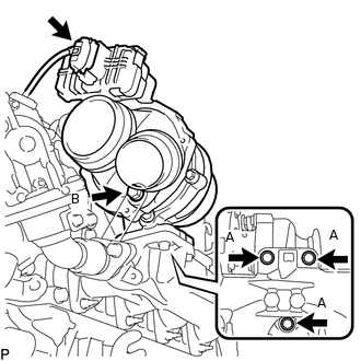
Temporarily install a new gasket, the turbocharger sub-assembly and the 3 bolts (A).
Temporarily install the bolt (B).
Tighten the 4 bolts.
for Bolt (A)
25 N*m
255 kgf*cm
18 ft.*lbf
for Bolt (B)
10 N*m
102 kgf*cm
7 ft.*lbf
Connect the connector to the turbocharger sub-assembly.
-
INSTALL NO. 1 EXHAUST MANIFOLD PIPE
Temporarily install the No. 1 exhaust manifold pipe with the bolt.
Temporarily install 2 new gaskets with the union bolt.
Tighten the bolt and union bolt.
for Bolt
8.0 N*m
82 kgf*cm
71 in.*lbf
for Union Bolt
35 N*m
357 kgf*cm
26 ft.*lbf
Connect the exhaust manifold pressure sensor connector.
CONNECT NO. 1 TURBO OIL PIPE
Connect the No. 1 turbo oil pipe and 2 new gaskets with the union bolt.
22 N*m
224 kgf*cm
16 ft.*lbf
INSTALL TURBO OIL OUTLET PIPE
Install a new O-ring to the turbo oil outlet pipe.
Install a new gasket and the turbo oil outlet pipe with the 3 bolts.
10 N*m
102 kgf*cm
7 ft.*lbf
CONNECT COMPRESSOR OUTLET ELBOW
-
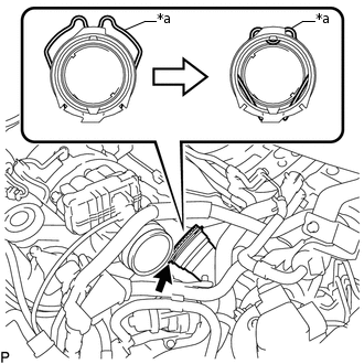
*a
Retainer
Connect the compressor outlet elbow to the turbocharger sub-assembly and lock the retainer as shown in the illustration.
-
INSTALL AIR CLEANER CASE SUB-ASSEMBLY
Install the air cleaner case sub-assembly with the 3 bolts.
7.0 N*m
71 kgf*cm
62 in.*lbf
INSTALL AIR CLEANER CAP SUB-ASSEMBLY WITH AIR CLEANER HOSE ASSEMBLY
Install the air cleaner filter element sub-assembly to the air cleaner case sub-assembly.
-
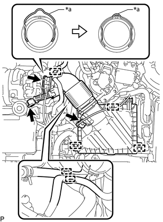
*a
Retainer
Connect the air cleaner hose assembly to the turbocharger sub-assembly and lock the retainer as shown in the illustration.
Attach the 2 clamps to install the air cleaner cap sub-assembly.
Connect the ventilation hose to the cylinder head cover sub-assembly.
Attach the clamp and connect the No. 2 fuel hose to the air cleaner hose assembly.
Attach the clamp and connect the No. 1 fuel hose to the air cleaner hose assembly.
Attach the clamp and connect the vacuum hose to the air cleaner hose assembly.
Attach the clamp and connect the mass air flow meter sub-assembly connector.
INSTALL BATTERY CARRIER
Install the battery carrier with the 4 bolts.
19 N*m
194 kgf*cm
14 ft.*lbf
Attach the 2 clamps to connect the engine wire.
INSTALL BATTERY TRAY
INSTALL BATTERY
INSTALL BATTERY INSULATOR
INSTALL BATTERY CLAMP SUB-ASSEMBLY
Attach the hook of the battery clamp sub-assembly to the battery carrier.
Partially tighten the nut and temporarily install the bolt.
Adjust the battery clamp sub-assembly position.
Tighten the nut and bolt.
for Bolt
17 N*m
173 kgf*cm
13 ft.*lbf
for Nut
3.5 N*m
36 kgf*cm
31 in.*lbf
INSTALL EXHAUST MANIFOLD CONVERTER SUB-ASSEMBLY
CONNECT CABLE FROM POSITIVE BATTERY TERMINAL
CONNECT CABLE FROM NEGATIVE BATTERY TERMINAL
Note:When disconnecting the cable, some systems need to be initialized after the cable is reconnected.
ADD ENGINE COOLANT
INSPECT FOR COOLANT LEAK