SFI SYSTEM, Diagnostic DTC:P0201,P0202,P0203,P0262,P0265 and P0268
| DTC Code | DTC Name |
|---|---|
| P0201 | Cylinder 1 Injector "A" Circuit |
| P0202 | Cylinder 2 Injector "A" Circuit |
| P0203 | Cylinder 3 Injector "A" Circuit |
| P0262 | Cylinder 1 Injector "A" Circuit High |
| P0265 | Cylinder 2 Injector "A" Circuit High |
| P0268 | Cylinder 3 Injector "A" Circuit High |
DESCRIPTION
The fuel injector assemblies are installed in the cylinder head and inject fuel into the cylinders based on the signals from the ECM.
DTC No. |
Detection Item |
DTC Detection Condition |
Trouble Area |
MIL |
Memory |
|---|---|---|---|---|---|
P0201 |
Cylinder 1 Injector "A" Circuit |
Open or short to ground in fuel injector assembly (No. 1 cylinder) circuit. |
|
Comes on |
DTC stored |
P0202 |
Cylinder 2 Injector "A" Circuit |
Open or short to ground in fuel injector assembly (No. 2 cylinder) circuit. |
|
Comes on |
DTC stored |
P0203 |
Cylinder 3 Injector "A" Circuit |
Open or short to ground in fuel injector assembly (No. 3 cylinder) circuit. |
|
Comes on |
DTC stored |
P0262 |
Cylinder 1 Injector "A" Circuit High |
Short to +B in fuel injector assembly (No. 1 cylinder) circuit. |
|
Comes on |
DTC stored |
P0265 |
Cylinder 2 Injector "A" Circuit High |
Short to +B in fuel injector assembly (No. 2 cylinder) circuit. |
|
Comes on |
DTC stored |
P0268 |
Cylinder 3 Injector "A" Circuit High |
Short to +B in fuel injector assembly (No. 3 cylinder) circuit. |
|
Comes on |
DTC stored |
MONITOR DESCRIPTION
These DTCs are stored when a malfunction is detected in a fuel injector assembly circuit. If there is an open or short in a fuel injector assembly circuit when the ignition switch is turned to ON, the ECM will illuminate the MIL and store a DTC.
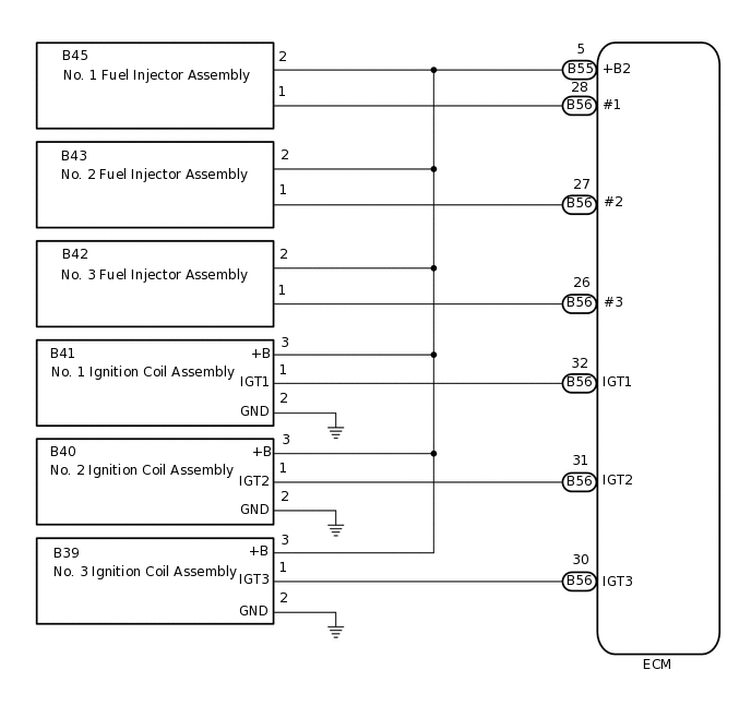
WIRING DIAGRAM
PROCEDURE
INSPECT FUEL INJECTOR ASSEMBLY
Inspect the fuel injector assembly.
Result
Proceed to
OK
NG
CHECK HARNESS AND CONNECTOR (FUEL INJECTOR ASSEMBLY - ECM)
Disconnect the fuel injector assembly connectors.
Disconnect the ignition coil assembly connectors.
Disconnect the ECM connectors.
Measure the resistance according to the value(s) in the table below.
Standard Resistance
Tester Connection
Condition
Specified Condition
B45-1 - B56-28 (#1)
Always
Below 1 Ω
B45-2 - B55-5 (+B2)
Always
Below 1 Ω
B43-1 - B56-27 (#2)
Always
Below 1 Ω
B43-2 - B55-5 (+B2)
Always
Below 1 Ω
B42-1 - B56-26 (#3)
Always
Below 1 Ω
B42-2 - B55-5 (+B2)
Always
Below 1 Ω
B45-1 or B56-28 (#1) - Body ground and other terminals
Always
10 kΩ or higher
B43-1 or B56-27 (#2) - Body ground and other terminals
Always
10 kΩ or higher
B42-1 or B56-26 (#3) - Body ground and other terminals
Always
10 kΩ or higher
B45-2, B43-2, B42-2, B41-3 (+B), B40-3 (+B), B39-3 (+B) or B55-5 (+B2) - Body ground and other terminals
Always
10 kΩ or higher
Result
Proceed to
OK
NG
NG REPAIR OR REPLACE HARNESS OR CONNECTOR