COUNTER GEAR REASSEMBLY

PROCEDURE
-
INSTALL COUNTER SHAFT 3RD GEAR
-
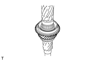
Apply manual transmission gear oil to the mounting point of the counter shaft, needle roller bearing and inside surface and taper cone of the counter shaft 3rd gear.
-
Install the needle roller bearing and counter shaft 3rd gear.
-
-
INSTALL NO. 2 TRANSMISSION HUB SLEEVE
-
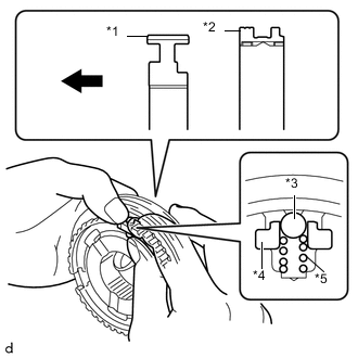
Text in Illustration *1 No. 2 Transmission Clutch Hub *2 No. 2 Transmission Hub Sleeve *3 Ball *4 No. 1 Synchromesh Shifting Key *5 No. 1 Synchromesh Shifting Key Spring 
Front Side Apply manual transmission gear oil to the moving parts of the No. 2 transmission clutch hub.
-
As shown in the illustration, install the No. 2 transmission hub sleeve to the No. 2 transmission clutch hub. Install the 3 No. 1 synchromesh shifting keys and 3 No. 1 synchromesh shifting key springs all together, and then install the balls.
Tech Tips
-
Install the shifting key ball while holding down the synchromesh shifting key spring. Install the ball while holding down the No. 1 synchromesh shifting key spring.
-
After the installation, let the No. 1 synchromesh shifting key spring settle down.
-
-
-
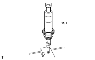
INSTALL NO. 2 TRANSMISSION CLUTCH HUB
-
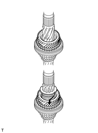
Install the No. 3 synchronizer ring set to the counter shaft 3rd gear.
Tech Tips
-
Align the middle ring claw with the groove in the counter shaft 3rd gear.
-
Align the inner ring claw with the groove in the outer ring.
-
-
Using SST and a press, install the No. 2 transmission clutch hub.
- SST
- 09316-60011 ( 09316-00011 )
Note
Make sure that the No. 3 synchronizer ring set is positioned properly.
Tech Tips
-
Align the No. 2 transmission clutch hub and the No. 3 synchronizer ring set so that they can fit together.
-
Make sure to press fit the No. 2 transmission clutch hub until it touches the counter shaft.
-
After the press fit, make sure that the No. 3 synchronizer ring set moves toward the thrust direction.
-
-
INSTALL COUNTER SHAFT 4TH GEAR
-
Install the No. 1 synchronizer ring to the No. 2 transmission clutch hub.
Tech Tips
Align the No. 2 transmission clutch hub and the No. 1 synchronizer ring so that they can fit together.
-
Apply manual transmission gear oil to the 4th gear bearing inner race and inside surface and taper cone of the counter shaft 4th gear.
-
Install the counter shaft 4th gear and 4th gear bearing inner race.
Tech Tips
To install it, rotate the 4th gear bearing inner race along the gear in a clockwise direction.
-
-
INSTALL 4TH INNER RACE THRUST WASHER
-
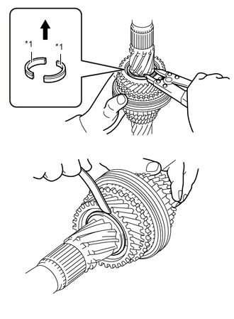
Text in Illustration *1 4th Inner Race Thrust Washer Front Side Select a 4th inner race thrust washer that is suitable to retain the specific thrust clearance between the 4th gear bearing inner race and 4th inner race thrust washer.
Standard clearance 0 to 0.1 mm (0 to 0.00394 in.) Tech Tips
Select the thickest 4th inner race thrust washer possible for installation.
4th Inner Race Thrust Washer Thickness Part No. Thickness mm (in.) Mark SU003-03500 3.75 (0.14763) A SU003-03501 3.80 (0.14960) B SU003-03502 3.85 (0.15157) C SU003-03503 3.90 (0.15354) D SU003-03504 3.95 (0.15551) E SU003-03505 4.00 (0.15748) F SU003-03506 4.05 (0.15944) G SU003-03507 4.10 (0.16141) H -
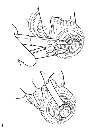
Using a snap ring expander, as shown in the illustration, install a new 4th inner race thrust washer, new 4th washer retaining ring and new shaft snap ring to the counter shaft.
-
-
INSTALL COUNTER DRIVE GEAR
-
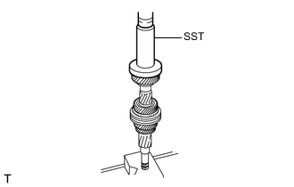
Using SST and a press, install the counter drive gear.
- SST
- 09309-36010
-
-
INSTALL SHAFT SNAP RING (for Counter Drive Gear)
-
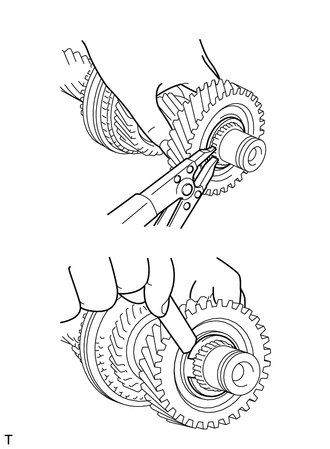
Select a shaft snap ring that is suitable to retain the specific thrust clearance between the counter drive gear and shaft snap ring.
Standard clearance 0 to 0.1 mm (0 to 0.00394 in.) Tech Tips
Select the thickest shaft snap ring possible for installation.
Shaft Snap Ring Thickness Part No. Thickness: mm (in.) Mark SU003-03581 1.80 (0.07086) A SU003-03582 1.85 (0.07283) B SU003-03583 1.90 (0.07480) C SU003-03584 1.95 (0.07677) D SU003-03585 2.00 (0.07874) E SU003-03586 2.05 (0.08070) F -
Using a snap ring expander, install a new shaft snap ring to the counter shaft.
-
-
INSTALL FRONT COUNTER GEAR BEARING
-
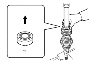
Text in Illustration *1 Front Counter Gear Bearing Front Side Using SST and a press, as shown in the illustration, install a new front counter gear bearing while holding it with your hand.
- SST
- 09330-50010
Note
Attach SST to the inner race of the front counter gear bearing, and then install the front counter gear bearing.
-
-
INSTALL SHAFT SNAP RING (for Front Counter Gear Bearing)
-
Select a shaft snap ring that is suitable to retain the specific thrust clearance between the counter gear front bearing and shaft snap ring.
Standard clearance 0 to 0.1 mm (0 to 0.00394 in.) Tech Tips
Select the thickest shaft snap ring possible for installation.
Shaft Snap Ring Thickness Part No. Thickness: mm (in.) Mark SU003-03560 2.05 (0.08070) 1 SU003-03558 2.10 (0.08267) 2 SU003-03561 2.15 (0.08464) 3 SU003-03559 2.20 (0.08661) 4 SU003-03562 2.25 (0.08858) 5 SU003-03563 2.30 (0.09055) 6 -
Using a snap ring expander, install a new shaft snap ring to the counter shaft.
-