ENGINE UNIT
-
CONSTRUCTION
-
A balance shaft is used to reduce vibrations.
-
The crankshaft directly drives the No. 1 balance shaft.
-
In addition, resin gears are used on the driven side to suppress noise and offer lightweight design.
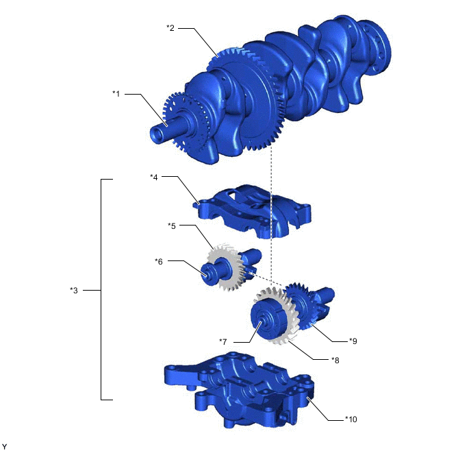
*1 Crankshaft *2 Balance Shaft Drive Gear *3 Engine Balancer Assembly *4 No. 2 Balance Shaft Housing *5 No. 3 Balance Shaft Driven Gear (Resin Gear) *6 No. 2 Balance Shaft *7 No. 1 Balance Shaft *8 No. 1 Balance Shaft Driven Gear (Resin Gear) *9 No. 2 Balance Shaft Driven Gear *10 No. 1 Balance Shaft Housing
-
-
OPERATION
-
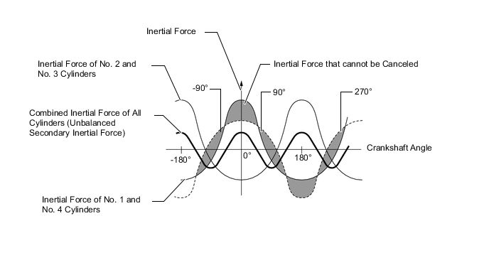
In the in-line 4-cylinder engine, the crankshaft angle for the No. 1 and No. 4 cylinders are at the exact opposite (180°) positions of the No. 2 and No. 3 cylinders. Therefore, the inertial force of the pistons and the connecting rods of the former 2 cylinders and of the latter 2 cylinders almost cancel each other out. However, because the position at which the piston reaches its maximum speed is located toward the top dead center from the center of the stroke, the upward inertial force is greater than the downward inertial force. This unbalanced secondary inertial force is generated twice for each rotation of the crankshaft.
Figure 1. Crankshaft Angle
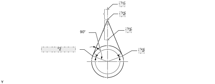
*1 Top Dead Center *2 Point of Max. Speed *3 Bottom Dead Center Figure 2. Inertial Force Generated by In-line 4 Cylinders
-
To cancel the unbalanced secondary inertial force, 2 balance shafts are rotated twice for each rotation of the crankshaft and generate inertial force in the opposite direction. Also, in order to cancel the inertial force generated by the balance shafts themselves, they are rotated in opposite directions.
Figure 3. Mass Direction of Balance Shaft at Crankshaft Angle
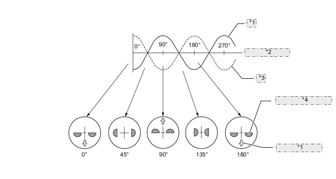
*1 Inertial Force of Balance Shaft *2 Crankshaft Angle *3 Secondary Inertial Force *4 Mass Direction of Balance Shaft
-