AIR CONDITIONING SYSTEM, Diagnostic DTC:B14B2
| DTC Code | DTC Name |
|---|---|
| B14B2 | Lost Communication with Front Panel LIN |
DESCRIPTION
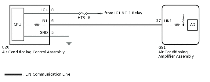
The air conditioning control assembly communicates with the air conditioning amplifier assembly through the LIN communication system.
If the LIN communication system malfunctions, the air conditioning amplifier assembly does not operate even if the air conditioning control assembly is operated.
DTC No. |
Detection Item |
DTC Detection Condition |
Trouble Area |
Memory |
Note |
|---|---|---|---|---|---|
B14B2 |
Lost Communication with Front Panel LIN |
Lost communication with the air conditioning control assembly. |
|
Memorized (10 seconds or more) |
- |
The air conditioning amplifier assembly stores the DTC of the respective malfunction if it has occurred for the period of time indicated in the parentheses.
WIRING DIAGRAM
CAUTION / NOTICE / HINT
Inspect the fuses for circuits related to this system before performing the following procedure.
When the servo motor or air conditioning amplifier assembly is replaced, be sure to perform servo motor initialization.
PROCEDURE
CHECK HARNESS AND CONNECTOR (AIR CONDITIONING CONTROL ASSEMBLY - BATTERY AND BODY GROUND)
-
*a
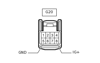
Front view of wire harness connector
(to Air Conditioning Control Assembly)
Disconnect the air conditioning control assembly connector.
Measure the resistance according to the value(s) in the table below.
Standard Resistance
Tester Connection
Condition
Specified Condition
G20-5 (GND) - Body ground
Always
Below 1 Ω
Measure the voltage according to the value(s) in the table below.
Standard Voltage
Tester Connection
Switch Condition
Specified Condition
G20-8 (IG+) - Body ground
Power switch off
Below 1 V
G20-8 (IG+) - Body ground
Power switch on (IG)
11 to 14 V
Result
Proceed to
OK
NG
NG REPAIR OR REPLACE HARNESS OR CONNECTOR
-
CHECK HARNESS AND CONNECTOR (AIR CONDITIONING CONTROL ASSEMBLY - AIR CONDITIONING AMPLIFIER ASSEMBLY)
Disconnect the G20 air conditioning control assembly connector.
Disconnect the G81 air conditioning amplifier assembly connector.
Measure the resistance according to the value(s) in the table below.
Standard Resistance
Tester Connection
Condition
Specified Condition
G20-6 (LIN1) - G81-37 (LIN1)
Always
Below 1 Ω
G20-6 (LIN1) or G81-37 (LIN1) - Body ground
Always
10 kΩ or higher
Result
Proceed to
OK
NG
NG REPAIR OR REPLACE HARNESS OR CONNECTOR
CHECK AIR CONDITIONING CONTROL ASSEMBLY
Replace the air conditioning control assembly.
When troubleshooting according to the DTC:
Clear the DTCs.
Body Electrical > Air Conditioner > Clear DTCs
Check for DTCs.
Body Electrical > Air Conditioner > Trouble Codes
OK
DTC B14B2 is not output.
Check the air conditioning control assembly operates normally.
Tip:Since the air conditioning control assembly cannot be inspected while it is removed from the vehicle, replace the air conditioning control assembly with a new or known good one and check that the condition returns to normal.
OK
Air conditioning control assembly operation returns to normal.
Result
Result
Proceed to
OK
A
NG (When troubleshooting according to Problem Symptoms Table)
B
NG (When troubleshooting according to the DTC)
C
A END (AIR CONDITIONING CONTROL ASSEMBLY WAS DEFECTIVE)