POWER BACK DOOR SYSTEM Power Back Door cannot be Operated Using Any Switch
| DTC Code | DTC Name |
|---|---|
| Power Back Door cannot be Operated Using Any Switch |
DESCRIPTION
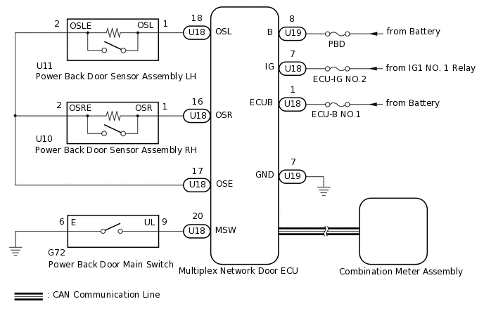
When the power back door cannot be operated using any switch, one of the following may be the cause: 1) initialization of the multiplex network door ECU, 2) power back door sensor assembly circuit, 3) power back door main switch circuit, 4) back door closer system, 5) meter/gauge system, 6) multiplex network door ECU power source circuit or 7) multiplex network door ECU.
WIRING DIAGRAM
CAUTION / NOTICE / HINT
First perform the communication function inspections in How to Proceed with Troubleshooting to confirm that there are no CAN communication malfunctions before troubleshooting this problem.
Inspect fuses for circuits related to this system before performing the following inspection procedure.
PROCEDURE
INITIALIZE MULTIPLEX NETWORK DOOR ECU
Perform the initialization for the multiplex network door ECU.
Result
Proceed to
NEXT
CHECK POWER BACK DOOR SYSTEM
Check power back door system operation.
Result
Proceed to
Power back door system operates normally
Power back door system does not operate
Power back door system operates normally END
CHECK BACK DOOR CLOSER SYSTEM
Check back door closer system operation.
Result
Proceed to
Back door closer system operates normally
Back door closer system does not operate
CHECK COMBINATION METER ASSEMBLY
Check shift position indicator operation and that the speedometer indicates 0 km/h (0 mph) when the vehicle is stopped and the engine is idling.
Result
Proceed to
Combination meter operates normally
Combination meter does not operate
CHECK FOR DTC
Check for DTCs.
Body Electrical > Back Door > Trouble Codes
Result
Proceed to
DTC is not output
DTCs are output
CHECK HARNESS AND CONNECTOR (MULTIPLEX NETWORK DOOR ECU - BATTERY AND BODY GROUND)
-
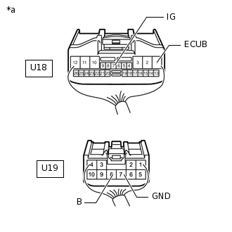
*a
Rear view of wire harness connector
(to Multiplex Network Door ECU)
Disconnect the multiplex network door ECU connectors.
Measure the resistance according to the value(s) in the table below.
Standard Resistance
Tester Connection
Condition
Specified Condition
U19-7 (GND) - Body ground
Always
Below 1 Ω
Measure the voltage according to the value(s) in the table below.
Standard Voltage
Tester Connection
Condition
Specified Condition
U18-1 (ECUB) - Body ground
Always
11 to 14 V
U19-8 (B) - Body ground
Always
11 to 14 V
U18-7 (IG) - Body ground
Ignition switch ON
11 to 14 V
U18-7 (IG) - Body ground
Ignition switch off
Below 1 V
Result
Proceed to
OK
NG
NG REPAIR OR REPLACE HARNESS OR CONNECTOR
-
READ VALUE USING GTS
Check the Data List to determine if the power back door sensor assembly functions properly.
Body Electrical > Back Door > Data List
Tester Display
Measurement Item
Range
Normal Condition
Diagnostic Note
PBD Touch Sensor (Right)
Power back door sensor assembly RH signal
ON, OFF or Open
ON: Power back door sensor assembly RH pressed
OFF: Power back door sensor assembly RH not pressed
Open: Power back door sensor assembly RH circuit open
-
PBD Touch Sensor (Left)
Power back door sensor assembly LH signal
ON, OFF or Open
ON: Power back door sensor assembly LH pressed
OFF: Power back door sensor assembly LH not pressed
Open: Power back door sensor assembly LH circuit open
-
Body Electrical > Back Door > Data List
Tester Display
PBD Touch Sensor (Right)
PBD Touch Sensor (Left)
Result
Result
Proceed to
On the GTS screen, ON or OFF is displayed accordingly
A
On the GTS screen, ON or OFF is not displayed accordingly or Open is displayed for power back door sensor assembly RH
B
On the GTS screen, ON or OFF is not displayed accordingly or Open is displayed for power back door sensor assembly LH
C
B INSPECT POWER BACK DOOR SENSOR ASSEMBLY RHClick here
C INSPECT POWER BACK DOOR SENSOR ASSEMBLY LHClick here
READ VALUE USING GTS
Check the Data List to determine if the power back door main switch functions properly.
Body Electrical > Back Door > Data List
Tester Display
Measurement Item
Range
Normal Condition
Diagnostic Note
PBD Main SW
Power back door main switch signal
ON or OFF
ON: Power back door main switch pushed
OFF: Power back door main switch not pushed
-
Body Electrical > Back Door > Data List
Tester Display
PBD Main SW
OK
The power back door main switch functions as specified in the normal condition column.
Result
Proceed to
OK
NG
NG INSPECT POWER BACK DOOR MAIN SWITCHClick here
INSPECT POWER BACK DOOR SENSOR ASSEMBLY RH
Remove the power back door sensor assembly RH.
Inspect the power back door sensor assembly RH.
Result
Proceed to
OK
NG
CHECK HARNESS AND CONNECTOR (POWER BACK DOOR SENSOR ASSEMBLY RH - MULTIPLEX NETWORK DOOR ECU)
Disconnect the U10 power back door sensor assembly RH connector.
Disconnect the U18 multiplex network door ECU connector.
Measure the resistance according to the value(s) in the table below.
Standard Resistance
Tester Connection
Condition
Specified Condition
U10-1 (OSR) - U18-16 (OSR)
Always
Below 1 Ω
U10-2 (OSRE) - U18-17 (OSE)
Always
Below 1 Ω
U10-1 (OSR) or U18-16 (OSR) - Body ground
Always
10 kΩ or higher
U10-2 (OSRE) or U18-17 (OSE) - Body ground
Always
10 kΩ or higher
Result
Proceed to
OK
NG
NG REPAIR OR REPLACE HARNESS OR CONNECTOR
INSPECT POWER BACK DOOR MAIN SWITCH
Remove the power back door main switch.
Inspect the power back door main switch.
Result
Proceed to
OK
NG
CHECK HARNESS AND CONNECTOR (POWER BACK DOOR MAIN SWITCH - MULTIPLEX NETWORK DOOR ECU AND BODY GROUND)
Disconnect the G72 power back door main switch connector.
Disconnect the U18 multiplex network door ECU connector.
Measure the resistance according to the value(s) in the table below.
Standard Resistance
Tester Connection
Condition
Specified Condition
G72-9 (UL) - U18-20 (MSW)
Always
Below 1 Ω
G72-6 (E) - Body ground
Always
Below 1 Ω
G72-9 (UL) or U18-20 (MSW) - Body ground
Always
10 kΩ or higher
Result
Proceed to
OK
NG
NG REPAIR OR REPLACE HARNESS OR CONNECTOR
INSPECT POWER BACK DOOR SENSOR ASSEMBLY LH
Remove the power back door sensor assembly LH.
Inspect the power back door sensor assembly LH.
Result
Proceed to
OK
NG
CHECK HARNESS AND CONNECTOR (POWER BACK DOOR SENSOR ASSEMBLY LH - MULTIPLEX NETWORK DOOR ECU)
Disconnect the U11 power back door sensor assembly LH connector.
Disconnect the U18 multiplex network door ECU connector.
Measure the resistance according to the value(s) in the table below.
Standard Resistance
Tester Connection
Condition
Specified Condition
U11-1 (OSL) - U18-18 (OSL)
Always
Below 1 Ω
U11-2 (OSLE) - U18-17 (OSE)
Always
Below 1 Ω
U11-1 (OSL) or U18-18 (OSL) - Body ground
Always
10 kΩ or higher
U11-2 (OSLE) or U18-17 (OSE) - Body ground
Always
10 kΩ or higher
Result
Proceed to
OK
NG
NG REPAIR OR REPLACE HARNESS OR CONNECTOR