DYNAMIC TORQUE CONTROL 4WD/AWD SYSTEM, Diagnostic DTC:C1297/97
| DTC Code | DTC Name |
|---|---|
| C1297/97 | Steering Angle Sensor |
DESCRIPTION
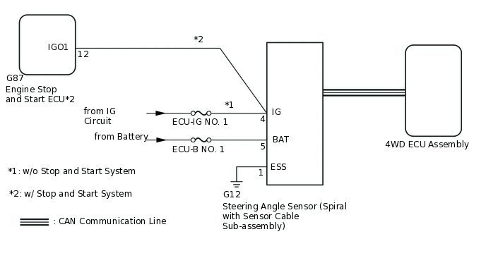
The 4WD ECU assembly determines that the vehicle is turning based on the signals sent from the steering angle sensor (spiral with sensor cable sub-assembly).
The steering angle sensor signal is sent to the 4WD ECU assembly via the CAN communication system.
DTC No. |
Detection Item |
DTC Detection Condition |
Trouble Area |
|---|---|---|---|
C1297/97 |
Steering Angle Sensor |
When voltage of 4WD ECU assembly IG terminal is 9.5 V or more, and steering angle sensor (spiral with sensor cable sub-assembly) malfunction signal is received. |
|
WIRING DIAGRAM
CAUTION / NOTICE / HINT
Inspect the fuses for circuits related to this system before performing the following inspection procedure.
PROCEDURE
CHECK FOR DTC
Clear the DTC.
Chassis > Four Wheel Drive > Clear DTCs
Turn the ignition switch off.
Turn the ignition switch to ON again and check that no CAN communication system DTC(s) is output.
for LHD:Click here
for RHD:Click here
Start the engine.
Drive the vehicle at a speed of 35 km/h (24 mph), turn the steering wheel to the right and left and check that no brake control system (steering angle sensor) DTC (C1432, C1433 or C1434) is output.
Chassis > ABS/VSC/TRC > Trouble Codes
Result
Result
Proceed to
Neither CAN communication system DTC nor brake control system DTC is output
A
CAN communication system DTC is output (for LHD)
B
CAN communication system DTC is output (for RHD)
C
Brake control system (steering angle sensor) DTC (C1432, C1433 or C1434) is output
D
Tip:When DTCs indicating a CAN communication system malfunction are output, repair the CAN communication system before repairing each corresponding sensor.
CHECK HARNESS AND CONNECTOR (POWER SOURCE TERMINAL)
-
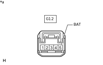
*a
Front view of wire harness connector
(to Steering Angle Sensor [Spiral with Sensor Cable Sub-assembly])
Remove the steering wheel and the column cover lower.
Make sure that there is no looseness at the locking part and the connecting part of the connectors.
Disconnect the steering angle sensor (spiral with sensor cable sub-assembly) connector.
Measure the voltage according to the value(s) in the table below.
Standard Voltage
Tester Connection
Condition
Specified Condition
G12-5 (BAT) - Body ground
Always
11 to 14 V
Result
Proceed to
OK
NG
NG REPAIR OR REPLACE HARNESS OR CONNECTOR
-
CHECK TERMINAL VOLTAGE (IG TERMINAL)
Turn the ignition switch to ON.
-
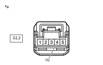
*a
Front view of wire harness connector
(to Steering Angle Sensor [Spiral with Sensor Cable Sub-assembly])
Measure the voltage according to the value(s) in the table below.
Standard Voltage
Tester Connection
Switch Condition
Specified Condition
G12-4 (IG) - Body ground
Ignition switch ON
11 to 14 V
Result
Proceed to
OK
NG (w/o Stop and Start System)
NG (w/ Stop and Start System)
NG (w/o Stop and Start System) REPAIR OR REPLACE HARNESS OR CONNECTOR (IG CIRCUIT)
NG (w/ Stop and Start System) INSPECT STOP AND START SYSTEM (BACKUP BOOST CONVERTER CIRCUIT)
CHECK HARNESS AND CONNECTOR (ESS TERMINAL)
-
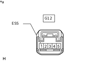
*a
Front view of wire harness connector
(to Steering Angle Sensor [Spiral with Sensor Cable Sub-assembly])
Turn the ignition switch off.
Measure the resistance according to the value(s) in the table below.
Standard Resistance
Tester Connection
Condition
Specified Condition
G12-1 (ESS) - Body ground
Always
Below 1 Ω
Result
Proceed to
OK
NG
NG REPAIR OR REPLACE HARNESS OR CONNECTOR
-
READ VALUE USING GTS (STEERING ANGLE VALUE)
Connect the GTS to the DLC3.
Turn the ignition switch to ON.
Turn the GTS on.
Enter the following menus: Chassis / Four Wheel Drive / Data List.
Read the value displayed on the GTS.
Chassis > Four Wheel Drive > Data List
Tester Display
Measurement Item
Range
Normal Condition
Diagnostic Note
Steering Angle Value
Steering angle value
Min.: -3276.8°
Max.: 3276.7°
Left turn: Increase
Right turn: Decrease
Changes in proportion with the amount of steering wheel rotation during steering operation.
Chassis > Four Wheel Drive > Data List
Tester Display
Steering Angle Value
OK
The steering angle sensor value changes in accordance with the steering wheel movement.
Result
Proceed to
OK
NG