MULTI-MODE MANUAL TRANSAXLE SYSTEM, Diagnostic DTC:P0919
| DTC Code | DTC Name |
|---|---|
| P0919 | Gear Shift Position Control Error |
DESCRIPTION
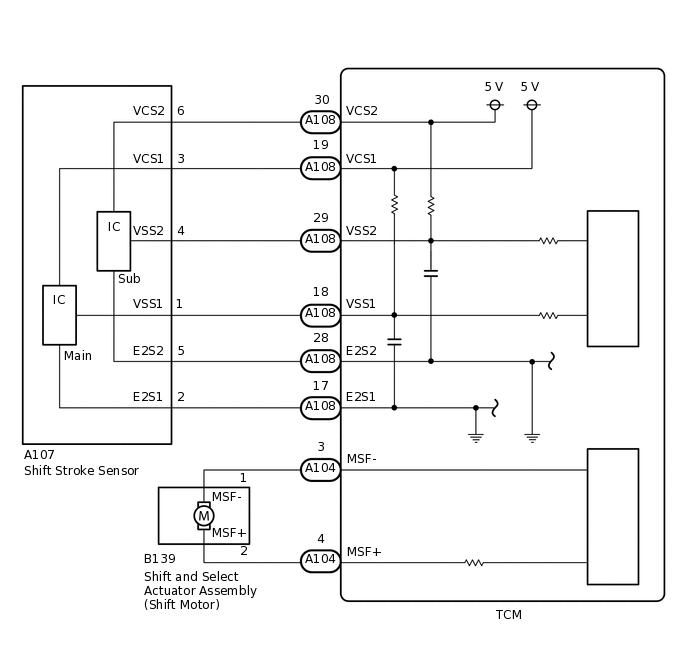
In the multi-mode manual transaxle system, the transaxle gear is shifted up and down by the TCM using a shift and select actuator. The shift and select actuator assembly consists of two motors (shift motor and select motor), stroke sensors (shift stroke sensor and select stroke sensor) and gears to move the shift and select lever shaft. The shift motor moves the shift and select lever shaft in the shift direction according to the signal from the TCM.
This DTC is stored in accordance with the stroke speed of the shift and select actuator or the difference between the target shift position and the actual shift position. Therefore, if malfunctions occur in the shift stroke sensor or the shift motor circuit, the DTCs relating to the sensor or motor circuit open/short (DTC P0915, P0916, P0917 and/or P0920) are stored before this DTC is stored.
DTC No. |
Detection Item |
DTC Detection Condition |
Trouble Area |
MIL |
Warning Indicate |
Memory |
|---|---|---|---|---|---|---|
P0919 |
Gear Shift Position Control Error |
The TCM detects the following conditions simultaneously for 2.0 seconds: (1-trip detection logic)
|
|
Does not come on |
Comes on |
DTC stored |
WIRING DIAGRAM
CAUTION / NOTICE / HINT
When installing parts related to the multi-mode manual transaxle system, perform the initialization and learning and synchronization position calibration procedures. In addition, the required operations differ according to the parts to be installed. Proceed with the operation in the order shown in the table below.
Part Installed |
Operation Order |
See Procedure |
|---|---|---|
|
1. Initialization and learning of multi-mode manual transaxle system |
|
2. Synchronization position calibration |
||
|
1. Initialization and learning of multi-mode manual transaxle system |
If the sensor or actuator is installed without the initialization and learning procedures, it may cause driving performance degradation or system component breakage.
If the symptom still occurs even after checking the following parts for dirt, wear, and defects and replacing the defective parts, replace the TCM.
Synchronizer rings
Shift forks
Hub sleeves
PROCEDURE
PERFORM ACTIVE TEST USING GTS (TARGET GEAR POSITION CONTROL)
Result
Proceed to
OK
NG
NG REPLACE SHIFT AND SELECT ACTUATOR ASSEMBLYClick here
INSPECT SHIFT STROKE SENSOR
Result
Proceed to
OK
NG
NG REPLACE SHIFT STROKE SENSORClick here
INSPECT TCM (MSF TERMINAL VOLTAGE)
Turn the ignition switch to ON.
-
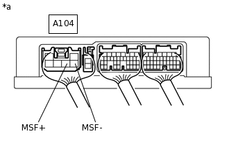
*a
Component with harness connected
(TCM)
Measure the voltage according to the value(s) in the table below.
Standard Voltage
Tester Connection
Condition
Specified Condition
A104-4 (MSF+) - Body ground
Ignition switch ON
4.0 to 7.0 V
A104-3 (MSF-) - Body ground
Ignition switch ON
4.0 to 7.0 V
Turn the ignition switch off.
Result
Proceed to
OK
NG
NG CHECK TERMINAL CONDITION (TCM)Click here
INSPECT TRANSAXLE ASSEMBLY
Result
Proceed to
OK
NG
NG REPAIR OR REPLACE DEFECTIVE PART IN TRANSAXLE ASSEMBLY
REPLACE TCM
Replace the TCM.
Result
Proceed to
NEXT
PERFORM INITIALIZATION
Perform the initialization and learning procedure.
Result
Proceed to
NEXT
NEXT CHECK HARNESS AND CONNECTOR (TCM - SHIFT MOTOR)
CHECK TERMINAL CONDITION (TCM)
Result
Proceed to
OK
NG
NG CONNECT CORRECTLY
CHECK SHIFT MOTOR CIRCUIT
-
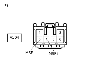
*a
Front view of wire harness connector
(to TCM)
Measure the resistance according to the value(s) in the table below.
Standard Resistance
Tester Connection
Condition
Specified Condition
A104-4 (MSF+) - A104-3 (MSF-)
Always
Below 10 Ω
A104-4 (MSF+) - Body ground
Always
10 kΩ or higher
A104-3 (MSF-) - Body ground
Always
10 kΩ or higher
Result
Proceed to
OK
NG
NG CHECK TERMINAL CONDITION (SHIFT MOTOR)Click here
-
REPLACE TCM
Replace the TCM.
Result
Proceed to
NEXT
CHECK TERMINAL CONDITION (SHIFT MOTOR)
Disconnect the shift motor connector.
Check the connections of the shift motor connector.
OK
The shift motor and wire harness connectors and connector terminals are connected securely and are not bent, rusted, or damaged.
Result
Proceed to
OK
NG
NG CONNECT CORRECTLY
CHECK HARNESS AND CONNECTOR (TCM - SHIFT MOTOR)
Measure the resistance according to the value(s) in the table below.
Standard Resistance
Tester Connection
Switch Condition
Specified Condition
A104-4 (MSF+) - B139-2 (MSF+)
Always
Below 1 Ω
A104-3 (MSF-) - B139-1 (MSF-)
Always
Below 1 Ω
A104-4 (MSF+) or B139-2 (MSF+) - Body ground
Always
10 kΩ or higher
A104-3 (MSF-) or B139-1 (MSF-) - Body ground
Always
10 kΩ or higher
Result
Proceed to
OK
NG
NG REPAIR OR REPLACE HARNESS OR CONNECTOR
INSPECT SHIFT AND SELECT ACTUATOR ASSEMBLY (SHIFT MOTOR)
-
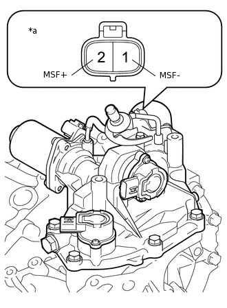
*a
Component without harness connected
(Shift and Select Actuator Assembly (Shift Motor))
Measure the resistance according to the value(s) in the table below.
Standard Resistance
Tester Connection
Condition
Specified Condition
1 (MSF-) - 2 (MSF+)
Always
Below 10 Ω
1 (MSF-) - Body ground
Always
10 kΩ or higher
2 (MSF+) - Body ground
Always
10 kΩ or higher
Result
Proceed to
OK
NG
NG REPLACE SHIFT AND SELECT ACTUATOR ASSEMBLYClick here
-
REPLACE SHIFT STROKE SENSOR
Replace the shift stroke sensor.
Result
Proceed to
NEXT
REPLACE SHIFT AND SELECT ACTUATOR ASSEMBLY
Replace the shift and select actuator assembly.
Result
Proceed to
NEXT