POWER BACK DOOR SYSTEM, Diagnostic DTC:B2205
| DTC Code | DTC Name |
|---|---|
| B2205 | Kick Sensor Circuit |
DESCRIPTION
B2205 is output when the multiplex network door ECU detects that the kick door control sensor is stuck on.
DTC No. |
Detection Item |
DTC Detection Condition |
Trouble Area |
|---|---|---|---|
B2205 |
Kick Sensor Circuit |
One of the following conditions is met for approximately 60 seconds or more:
|
|
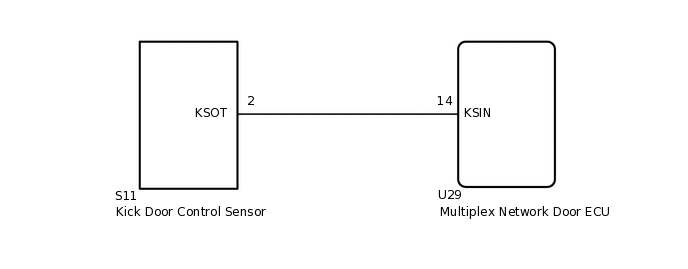
WIRING DIAGRAM
CAUTION / NOTICE / HINT
Before troubleshooting, make sure that the kick door control sensor is not damaged.
Before troubleshooting, be sure to read Precautions for Touchless Power Back Door.
If the multiplex network door ECU has been removed and installed or replaced, or if any of the connectors has been disconnected, initialize the power back door system.
After performing work, using the GTS, read the Data List item "Kick Sensor Connection" and check that the kick door control sensor is connected.
PROCEDURE
CHECK FOR DTC
Clear the DTCs.
Body Electrical > Back Door > Clear DTCs
Check for DTCs.
Body Electrical > Back Door > Trouble Codes
Result
Result
Proceed to
DTC is not output
A
DTC B2205 is output
B
CHECK FOR DTC
Disconnect the S11 kick door control sensor connector.
Wait for approximately 60 seconds.
Clear the DTCs.
Body Electrical > Back Door > Clear DTCs
Check for DTCs.
Body Electrical > Back Door > Trouble Codes
Result
Result
Proceed to
DTC is not output
A
DTC B2205 is output
B
CHECK HARNESS AND CONNECTOR (MULTIPLEX NETWORK DOOR ECU - KICK DOOR CONTROL SENSOR)
Disconnect the U29 multiplex network door ECU connector.
Disconnect the S11 kick door control sensor connector.
Measure the resistance according to the value(s) in the table below.
Standard Resistance
Tester Connection
Condition
Specified Condition
U29-14 (KSIN) or S11-2 (KSOT) - Body ground
Always
10 kΩ or higher
Result
Proceed to
OK
NG
NG REPAIR OR REPLACE HARNESS OR CONNECTOR