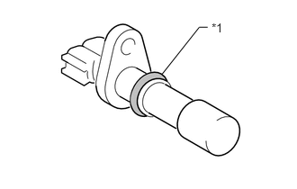
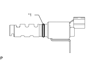
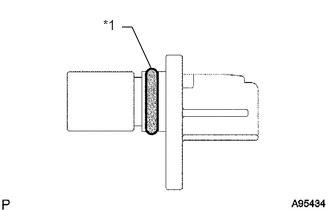
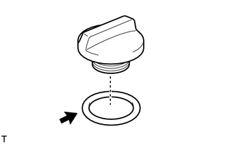
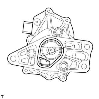
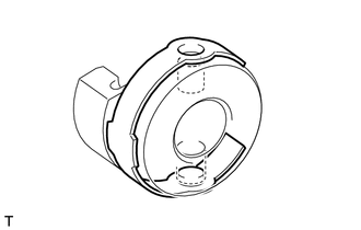
Install a new O-ring to the continuously variable valve lift controller.
Table 2. Text in Illustration
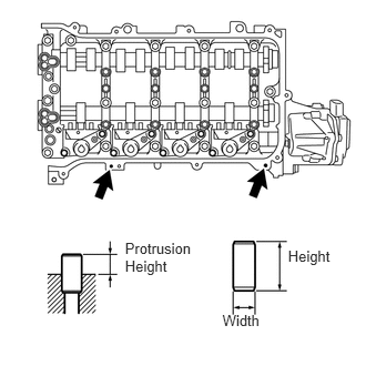
*1
Protrusion
Note:
Align the protrusion of the O-ring with the protrusion of the continuously variable valve lift controller.
Make sure that the O-ring is not protruding from the groove in the continuously variable valve lift controller.
Install the control actuator clip to the control actuator connector.
Tip:
When the continuously variable valve lift controller is new, a control actuator connector is attached to it. Remove the control actuator connector before performing these procedures.
Note:
Be sure to insert the protrusions of the control actuator clip into the holes in the control actuator connector.
Install the valve lift control actuator connector to the valve rocker shaft.
Tip:
There are two types of valve lift control actuator connectors. One type is installed by rotating the connector, and the other type can be installed without being rotated.
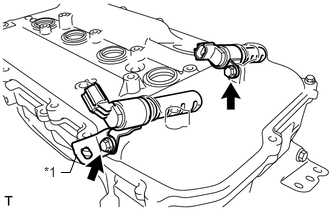
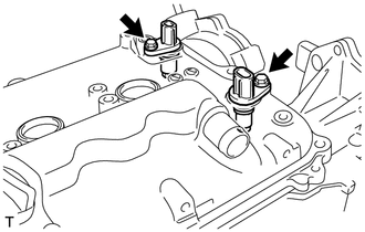
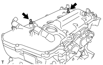
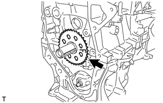
Insert the continuously variable valve lift controller into the camshaft housing.
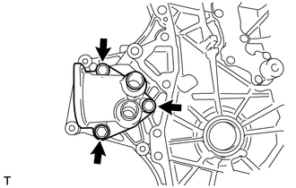
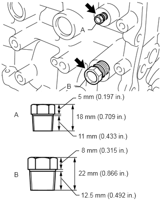
Install the continuously variable valve lift controller to the camshaft housing with the bolt.
18 N*m
184 kgf*cm
13 ft.*lbf
Note:
Do not let the O-ring become jammed between parts.
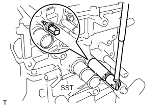
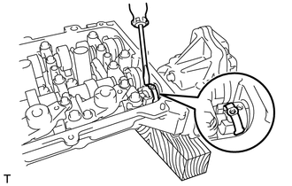
Using a screwdriver, slide the control actuator clip from the control actuator connector.
Slide only the upper part of the control actuator clip as the straight pin may fall if the control actuator clip is completely removed.
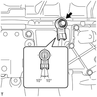
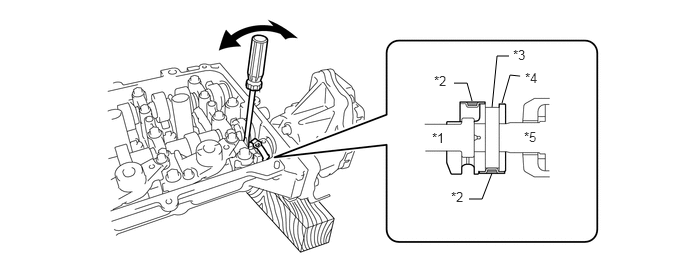
Using a screwdriver, lightly pry the control actuator connector and align the hole in the control actuator connector with the hole in the continuously variable valve lift controller.
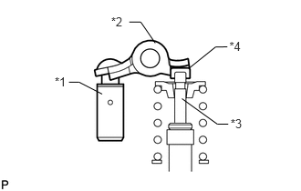
Table 3. Text in Illustration
*1
Rocker Shaft
*2
Clip
*3
Straight Pin Hole
*4
Connector
*5
Controller Shaft
Note:
Do not forcefully pry the control actuator connector.
Do not damage the camshaft housing or camshaft bearing cap.
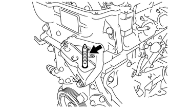
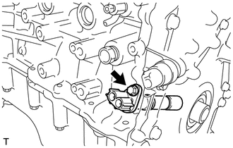
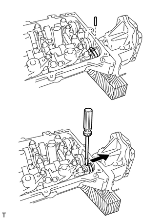
Insert the straight pin into the control actuator connector.
Note:
Do not use a tool to insert the straight pin. Insert the straight pin by hand.
Tip:
If the straight pin is difficult to insert, insert the straight pin while lightly prying the control actuator connector.
Using a screwdriver, install the control actuator clip to the control actuator connector.
Note:
Insert the protrusion of the control actuator clip into the hole in the control actuator connector.
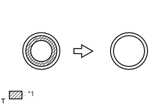
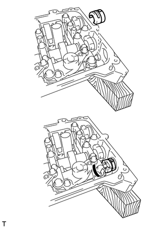
Using a cutter knife, cut off the seal part of the removed gasket.
Table 4. Text in Illustration
*1
Part to Cut Off
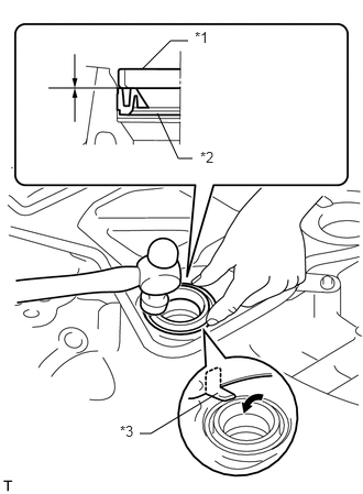
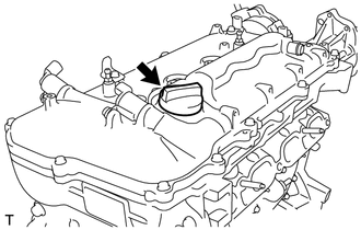
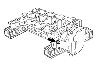
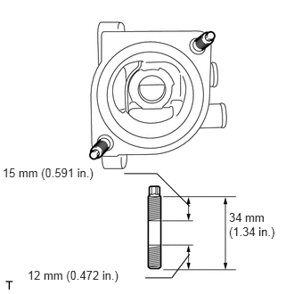
Using a hammer and a plug tube gasket which has had the sealing part cut off, uniformly tap in a new plug tube gasket all the way.
Table 5. Text in Illustration
*1
Plug Tube Gasket without Sealing Part
*2
New Plug Tube Gasket
*3
Claw
Tip:
If a plug tube gasket that will be used to install a new gasket is deformed and cannot be positioned on a new gasket, correct the deformation using pliers.
Note:
Keep the lip free of foreign matter.
Do not tap in the plug tube gasket at an angle.
Return the claws of the ventilation baffle plate to their original positions.
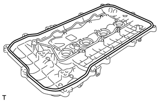
INSTALL CYLINDER HEAD COVER GASKET
Install a new cylinder head cover gasket to the cylinder head cover.
Note:
Remove any oil from the contact surfaces.
INSTALL CYLINDER HEAD COVER SUB-ASSEMBLY
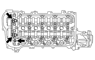
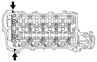
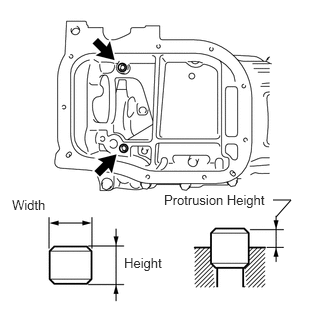
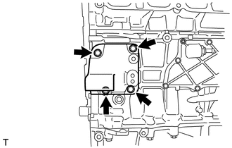
Install 3 new gaskets to the camshaft bearing cap.
Apply seal packing as shown in the illustration.
Seal packing
Toyota Genuine Seal Packing Black, Three Bond 1207B or equivalent
Standard diameter
4.0 mm (0.157 in.)
Note:
Remove any oil from the contact surfaces.
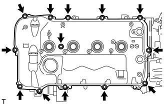
Install the cylinder head cover sub-assembly within 3 minutes and tighten the bolts within 15 minutes after applying seal packing.
Do not start the engine for at least 2 hours after the installation.
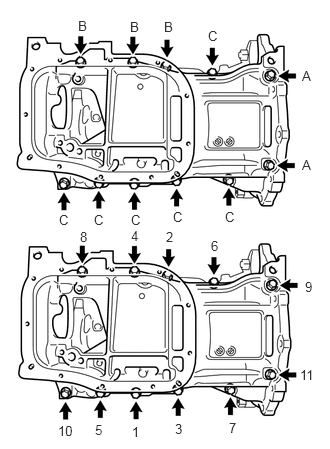
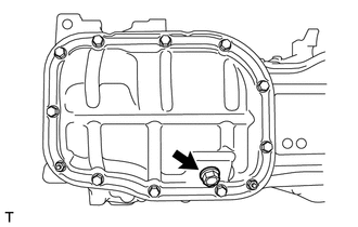
Install the cylinder head cover with a new seal washer and the 13 bolts.
 Note:
Note: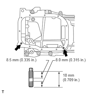 Note:
Note: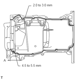
 Note:
Note:
 Note:
Note: