FRONT DOOR(for Sedan) DISASSEMBLY
CAUTION / NOTICE / HINT
Use the same procedure for both the RH and LH sides.
The procedure described below is for the LH side.
PROCEDURE
PRECAUTION
Note:After turning the ignition switch off, waiting time may be required before disconnecting the cable from the negative (-) battery terminal. Therefore, make sure to read the disconnecting the cable from the negative (-) battery terminal notices before proceeding with work.
DISCONNECT CABLE FROM NEGATIVE BATTERY TERMINAL
Note:When disconnecting the cable, some systems need to be initialized after the cable is reconnected.
REMOVE DOOR ASSIST GRIP COVER
-
Using a moulding remover, disengage the 10 claws and remove the door assist grip cover.
-
REMOVE FRONT ARMREST ASSEMBLY
-
Using a moulding remover, disengage the 2 clips and 5 claws and remove the front armrest assembly.
-
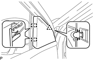
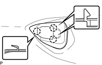
REMOVE POWER WINDOW REGULATOR MASTER SWITCH ASSEMBLY WITH FRONT DOOR ARMREST BASE PANEL (for Driver Side)
-
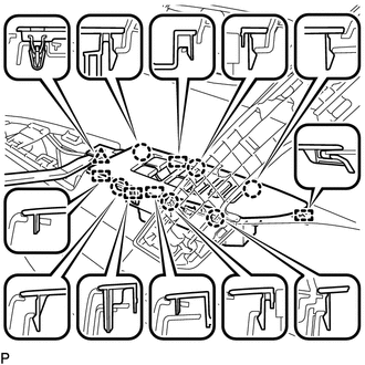
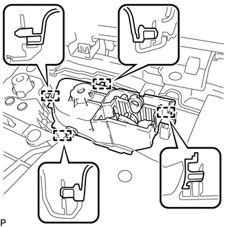
Using a moulding remover, disengage the clip, 6 claws and 5 guides as shown in the illustration.
Disconnect the connector and remove the power window regulator master switch assembly with front door armrest base panel.
-
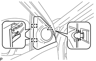
REMOVE POWER WINDOW REGULATOR SWITCH ASSEMBLY WITH FRONT DOOR ARMREST BASE PANEL (for Front Passenger Side)
-
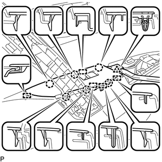
Using a moulding remover, disengage the clip, 6 claws and 5 guides as shown in the illustration.
Disconnect the connector and remove the power window regulator switch assembly with front door armrest base panel.
-
REMOVE FRONT DOOR LOWER FRAME BRACKET GARNISH
w/o Front No. 2 Speaker:
-
Disengage the clip and 2 guides and remove the front door lower frame bracket garnish.
-
w/ Front No. 2 Speaker:
-
Disengage the clip and 2 guides.
Disconnect the connector and remove the front door lower frame bracket garnish.
-
REMOVE FRONT NO. 2 SPEAKER ASSEMBLY (w/ Front No. 2 Speaker)
REMOVE FRONT DOOR TRIM BOARD SUB-ASSEMBLY
-
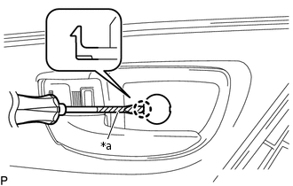
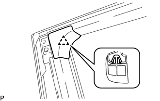
*a
Protective Tape
Using a screwdriver with its tip wrapped in protective tape, disengage the claw and open the cover.
-

Protective Tape
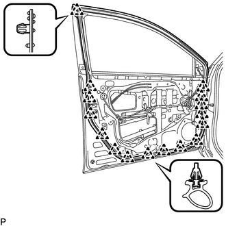
Put protective tape around the front door panel.
-
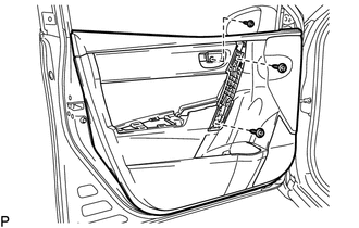
Remove the 3 screws.
-
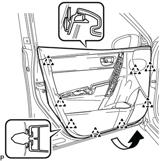
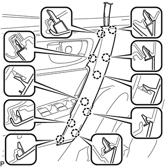
Disengage the 8 clips and remove the front door trim board sub-assembly as shown in the illustration.
-
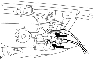
Disconnect the front door lock remote control cable assembly and front door inside locking cable assembly.
-
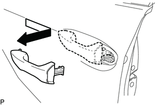
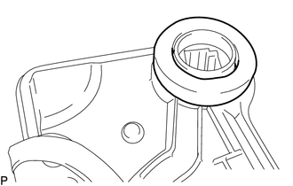
REMOVE FRONT DOOR INSIDE HANDLE SUB-ASSEMBLY
-
Disengage the 4 guides and remove the front door inside handle sub-assembly.
-
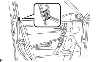
REMOVE FRONT DOOR INNER GLASS WEATHERSTRIP
-
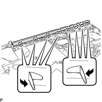
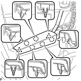
Disengage the 8 claws as shown in the illustration and remove the front door inner glass weatherstrip.
-
REMOVE OUTER REAR VIEW MIRROR ASSEMBLY WITH COVER
REMOVE FRONT NO. 1 SPEAKER ASSEMBLY
REMOVE FRONT DOOR SERVICE HOLE COVER
-
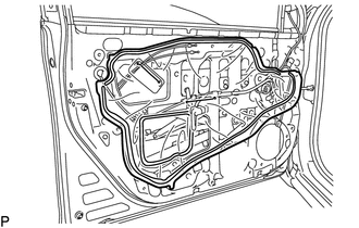
Remove the front door service hole cover.
Tip:Remove any remaining butyl tape from the door.
-
REMOVE FRONT DOOR GLASS SUB-ASSEMBLY
Connect the cable to the negative (-) battery terminal.
for Driver Side:
Connect the power window regulator master switch assembly and move the front door glass sub-assembly so that the door glass bolts can be seen.
for Front Passenger Side:
Connect the power window regulator switch assembly and move the front door glass sub-assembly so that the door glass bolts can be seen.
Disconnect the cable from the negative (-) battery terminal.
for Driver Side:
Disconnect the power window regulator master switch assembly.
for Front Passenger Side:
Disconnect the power window regulator switch assembly.
-
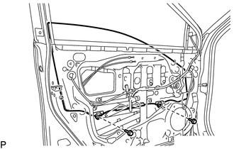
Remove the 2 bolts.
Note:After the bolts are removed, do not allow the front door glass sub-assembly to fall.
-
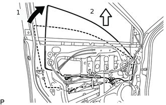
Remove the front door glass sub-assembly as indicated by the arrows, in the order shown in the illustration.
Note:Do not damage the front door glass sub-assembly.
REMOVE FRONT DOOR WINDOW REGULATOR ASSEMBLY
-
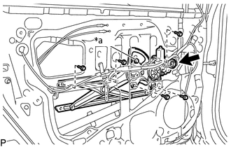
*a
Temporary Bolt
Disconnect the connector.
Loosen the temporary bolt.
Note:Do not remove the temporary bolt. If the temporary bolt is removed, the front door window regulator may fall and cause damage.
Remove the 5 bolts.
Remove the front door window regulator assembly.
Remove the temporary bolt from the front door window regulator assembly.
-
REMOVE FRONT DOOR GLASS RUN
-
Remove the front door glass run.
-
REMOVE FRONT DOOR REAR LOWER FRAME SUB-ASSEMBLY
-
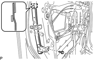
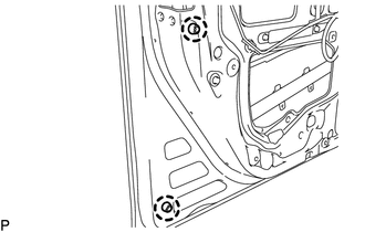
Remove the bolt.
Disengage the guide and remove the front door rear lower frame sub-assembly.
-
REMOVE FRONT DOOR OUTSIDE HANDLE COVER WITH LOCK CYLINDER ASSEMBLY (for Driver Side)
-
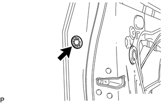
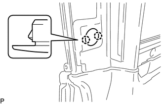
Remove the hole plug.
-
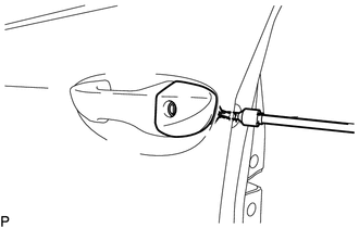
Using a T30 "TORX" socket wrench, loosen the screw and remove the front door outside handle cover with lock cylinder assembly.
Tip:The screw cannot be removed because it is integrated into the front door outside handle frame sub-assembly.
-
REMOVE FRONT DOOR OUTSIDE HANDLE COVER (for Driver Side)
-
Using a screwdriver, disengage the claw and 2 guides, and remove the front door outside handle cover as shown in the illustration.
-
REMOVE FRONT DOOR OUTSIDE HANDLE COVER (for Front Passenger Side)
-

Remove the hole plug.
-
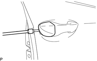
Using a T30 "TORX" socket wrench, loosen the screw and remove the front door outside handle cover.
Tip:The screw cannot be removed because it is integrated into the front door outside handle frame sub-assembly.
-
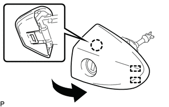
REMOVE FRONT DOOR OUTSIDE HANDLE ASSEMBLY
w/ Entry and Start System:
-
Disengage the 2 claws.
Using a screwdriver, disconnect the connector.
-
-
Remove the front door outside handle assembly as shown in the illustration.
REMOVE FRONT DOOR FRONT OUTSIDE HANDLE PAD
-
Disengage the 3 claws and remove the front door front outside handle pad.
-
REMOVE FRONT DOOR REAR OUTSIDE HANDLE PAD
-
Disengage the 2 claws and remove the front door rear outside handle pad.
-
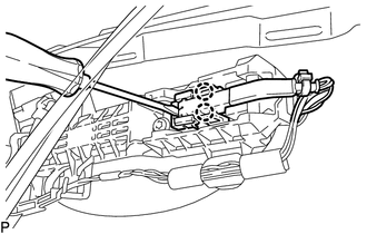
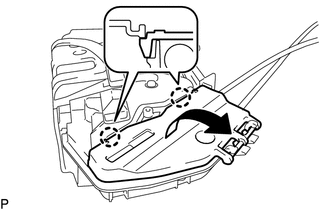
REMOVE FRONT DOOR LOCK WITH MOTOR ASSEMBLY
-
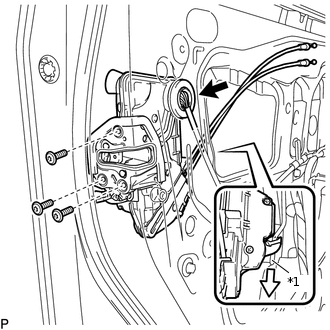
*1
Front Door Lock Open Rod
Disconnect the connector.
Using a T30 "TORX" socket wrench, remove the 3 screws.
Slide the front door lock with motor assembly downward, and remove the front door lock with motor assembly and cables as a unit.
When reusing the front door lock with motor assembly:
-
Remove the door lock wiring harness seal from the front door lock with motor assembly.
-
-
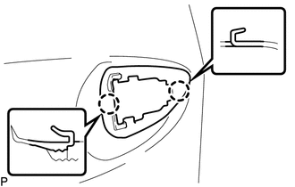
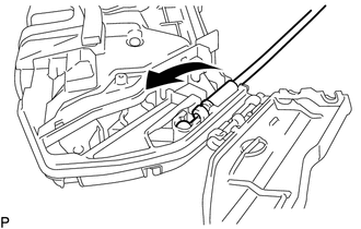
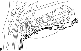
REMOVE FRONT DOOR LOCK REMOTE CONTROL CABLE ASSEMBLY
-
Using a screwdriver, disengage the 2 claws as shown in the illustration.
-
Remove the front door lock remote control cable assembly as shown in the illustration.
-
REMOVE FRONT DOOR INSIDE LOCKING CABLE ASSEMBLY
-
Remove the front door inside locking cable assembly as shown in the illustration.
-
REMOVE FRONT DOOR OUTSIDE HANDLE FRAME SUB-ASSEMBLY
w/ Entry and Start System:
-
Disengage the 3 clamps.
-
-
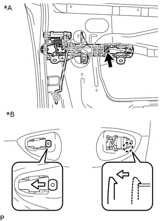
*A
Inside
*B
Outside
Using a T30 "TORX" socket wrench, remove the screw.
Slide the front door outside handle frame sub-assembly to disengage the claw of the front door outside handle frame sub-assembly, and then remove it.
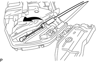
REMOVE FRONT DOOR LOCK OPEN ROD
-
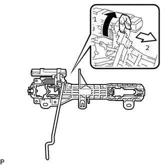
Remove the front door lock open rod as indicated by the arrows, in the order shown in the illustration.
-
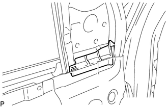
REMOVE FRONT DOOR CHECK ASSEMBLY
-
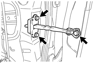
Remove the 3 bolts and front door check assembly.
-
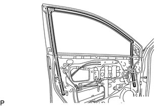
REMOVE FRONT DOOR WEATHERSTRIP
-
Using a clip remover, disengage the 16 clips and remove the front door weatherstrip.
-
REMOVE DOOR FRAME GARNISH
-
Disengage the clip and remove the door frame garnish.
Tip:This garnish needs to be replaced with a new one because the clip will break when removing it.
-
REMOVE DOOR WINDOW FRAME MOULDING CLIP
-
Disengage the 2 claws and remove the door window frame moulding clip.
-
REMOVE FRONT DOOR PANEL CUSHION
-
Disengage the 2 claws and remove the 2 front door panel cushions.
-
REMOVE FRONT DOOR VENT SEAL
-
Remove the front door vent seal.
-
REMOVE FRONT DOOR BELT MOULDING ASSEMBLY
REMOVE FRONT DOOR REAR WINDOW FRAME MOULDING
REMOVE NO. 1 BLACK OUT TAPE