AIRBAG SYSTEM DIAGNOSIS SYSTEM
CHECK DLC3
Check the DLC3.
FUNCTION OF SRS WARNING LIGHT
Primary check
Turn the ignition switch off. Wait for at least 2 seconds, then turn the ignition switch to ON. The SRS warning light comes on for approximately 6 seconds and diagnosis of the airbag system (including the seat belt pretensioners) is performed.
Tip:If malfunctions are detected during the primary check, the SRS warning light remains on even after the primary check period of approximately 6 seconds.
Constant check
After the primary check, the airbag sensor assembly constantly monitors the airbag system for malfunctions.
Tip:If malfunctions are detected during the constant check, the airbag sensor assembly will indicate the malfunction as follows:
The SRS warning light comes on.
The SRS warning light goes off, and then comes on. This indicates a source voltage drop. The SRS warning light goes off 10 seconds after the source voltage returns to normal.
Review
When the airbag system is normal:
The SRS warning light comes on only during the primary check period of approximately 6 seconds after the ignition switch is turned to ON.
When the airbag system is malfunctioning:
The SRS warning light remains on even after the primary check period.
The SRS warning light goes off after the primary check, but comes on again during the constant check.
The SRS warning light does not come on when the ignition switch is turned from off to ON.
Tip:The airbag sensor assembly keeps the SRS warning light on if airbags have been deployed.
SRS WARNING LIGHT CHECK
-
Turn the ignition switch to ON, and check that the SRS warning light comes on for approximately 6 seconds (primary check).
Check that the SRS warning light goes off approximately 6 seconds after the ignition switch is turned to ON (constant check).
Tip:When any of the following symptoms occur, refer to Problem Symptoms Table.
The SRS warning light comes on occasionally after the primary check period.
The SRS warning light comes on, but DTCs are not output.
The ignition switch is turned from off to ON, but the SRS warning light does not come on.
-
FUNCTION OF PASSENGER AIRBAG ON/OFF INDICATOR
Initial check
Turn the ignition switch to ON.
The passenger airbag ON/OFF indicator comes on for approximately 4 seconds, then goes off for approximately 2 seconds.
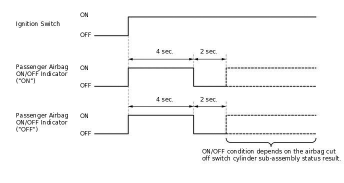
Approximately 6 seconds after the ignition switch is turned to ON, the passenger airbag ON/OFF indicator will indicate ON/OFF according to the airbag cut off switch cylinder sub-assembly condition as listed below.
Table 1. Indicator Operation Airbag Cut Off Switch Cylinder Sub-assembly Condition
Passenger Airbag ON/OFF Indicator
SRS Warning Light
ON Indicator
OFF Indicator
ON
ON
OFF
OFF
OFF
OFF
ON
OFF
Switch failure
OFF
ON
ON
Tip:If the passenger airbag ON/OFF indicator does not operate as specified in the table according to the airbag cut off switch cylinder sub-assembly status, and the SRS warning light is off, no DTC will be output. Therefore, perform troubleshooting for Trouble in Passenger Airbag ON/OFF Indicator.
PASSENGER AIRBAG ON/OFF INDICATOR CHECK
-
Turn the ignition switch to ON.
Check that the passenger airbag ON/OFF indicator ("ON" and "OFF") comes on for approximately 4 seconds, then goes off for approximately 2 seconds.
Tip:Refer to the indicator operation table in the preceding step regarding the passenger airbag ON/OFF indicator when the ignition switch is turned to ON and approximately 6 seconds elapse.
-
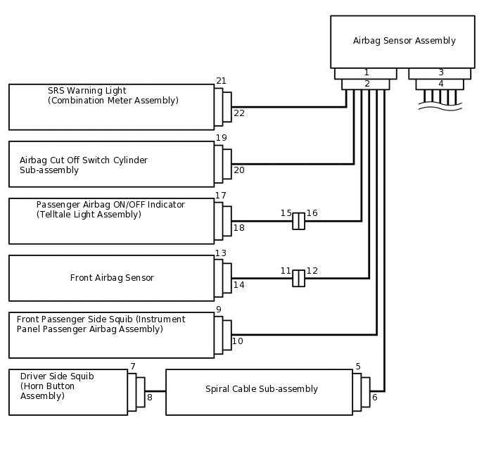
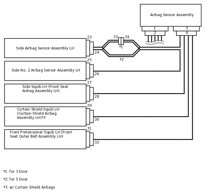
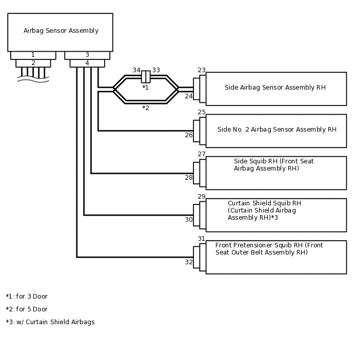
FUNCTION OF SRS CONNECTORS
The SRS connectors are located as shown in the illustration.
Connector Type
Application
Terminal Twin-lock Mechanism
Connectors 2, 4, 6, 9, 10, 12, 15, 16, 18, 20, 22, 28, 34
Half Connection Prevention Mechanism
Connectors 6, 10
Activation Prevention Mechanism
Connectors 2, 4, 5, 7, 9, 27, 29, 31
Connector Lock Mechanism (1)
Connectors 8, 30, 32
Connector Position Assurance Mechanism
Connectors 11, 14, 24, 26, 33
Connector Lock Mechanism (2)
Connectors 2, 4
Improper Connection Prevention Lock Mechanism
Connectors 2, 4
Terminal twin-lock mechanism
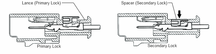
This mechanism is designed to increase the ability of the terminal to remain connected and prevent it from accidentally being disconnected.
The connector has a two-piece construction consisting of the housing and spacer to securely lock the terminal using both the lance (primary lock) and spacer (secondary lock).
Half connection prevention mechanism
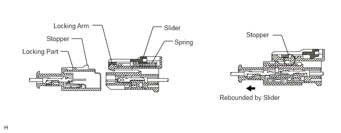
This mechanism is designed to prevent the connector from being connected only halfway.
If the connector is not completely connected, the connector is disconnected due to the spring force so that no continuity exists.
Activation prevention mechanism
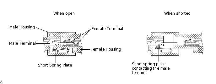
This mechanism is designed to create a short circuit automatically between the positive and negative terminals of an airbag power source connector when disconnected.
The short spring plate contained in the connector creates a closed circuit on the airbag side (no potential difference can occur between both terminals), preventing accidental airbag deployment when servicing.
Connector lock mechanism (1)
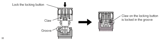
This mechanism is designed to prevent the connector from accidentally being disconnected.
Locking the connector locking button engages the locking button claws in the grooves on the other side of the connector to connect the connector securely.
Connector Position Assurance (CPA) mechanism
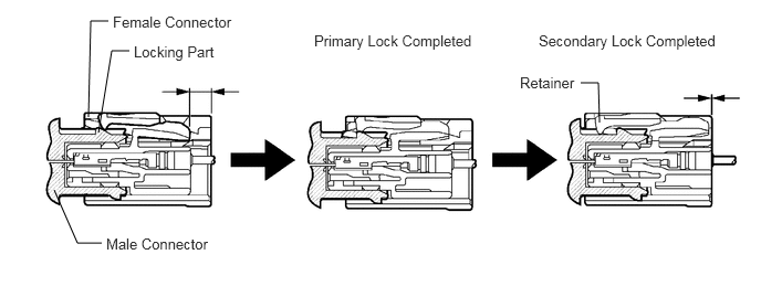
This mechanism is designed to detect when the connector is connected only halfway.
The CPA and female connector slide to the male connector side at the same time and the primary lock is completed when the female connector is engaged with the male connector. From this point, only the CPA slides to the male connector side and secondary lock is completed when the CPA retainer is engaged with the female connector. When the CPA and female connector ends are aligned, they are completely engaged.
Connector lock mechanism (2)
Function of this mechanism
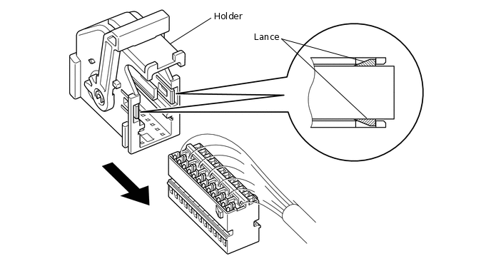
This mechanism is designed to prevent the connector from being disconnected.
Sliding the connector all the way into the holder and locking the lances completes the lock.
Removing of the holder
-
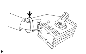
Remove the band.
-
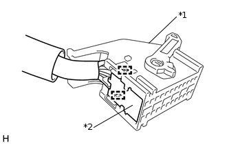
*1
Holder
*2
Connector
Disengage the 2 lances and slide the connector to remove the holder.
-
Improper connection prevention lock mechanism
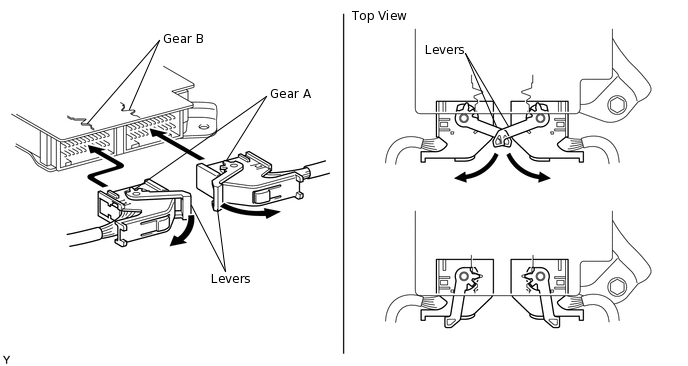
This mechanism is designed to prevent the connector from being connected only halfway.
Engage the gear (A) located on the tip of the lever with gear (B) of the airbag sensor assembly by pulling the lever. Locking the lever to the holder connects the connector securely.
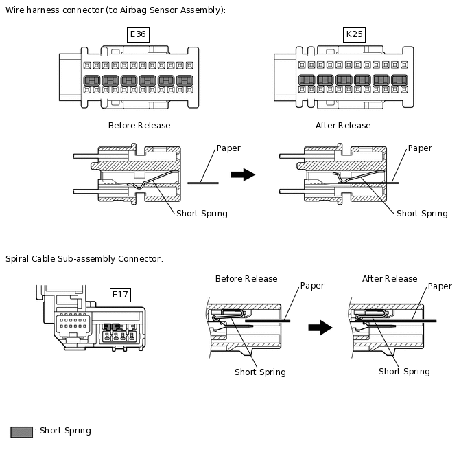
ACTIVATION PREVENTION MECHANISM
Function of activation prevention mechanism
An activation prevention mechanism is built into the connector of the airbag system squib circuit to prevent accidental airbag and pretensioner activation.
This mechanism closes the circuit when the connector is disconnected by bringing the short spring into contact with the terminals and insulating the circuit from external power sources to prevent accidental airbag and pretensioner activation.
Releasing of activation prevention mechanism
To release the activation prevention mechanism, insert a piece of paper with the same thickness as the male terminal (approximately 0.5 mm (0.0197 in.)) between the terminals and short spring to break the connection.
Refer to the following illustrations concerning connectors utilizing the activation prevention mechanism and its release method.
CAUTION:Never release the activation prevention mechanism on the squib connector even when inspecting with the squib disconnected.
Note:Do not release the activation prevention mechanism unless specifically directed by the troubleshooting procedure.
To prevent the terminal and short spring from being damaged, always use a piece of paper with the same thickness as the male terminal.