FUEL INJECTOR(for Direct Injection) REMOVAL

CAUTION / NOTICE / HINT
The necessary procedures (adjustment, calibration, initialization or registration) that must be performed after parts are removed and installed, or replaced during direct fuel injector assembly removal/installation are shown below.
| Replaced Part or Performed Procedure | Necessary Procedure | Effect/Inoperative Function when Necessary Procedure not Performed | Link |
|---|---|---|---|
| Battery terminal is disconnected/reconnected | Perform steering sensor zero point calibration | Lane Departure Alert System (w/ Steering Control) | |
| Pre-collision System | |||
| Memorize steering angle neutral point | Parking Assist Monitor System | ||
| Panoramic View Monitor System | |||
|
Inspection after repair |
|
CAUTION:
-
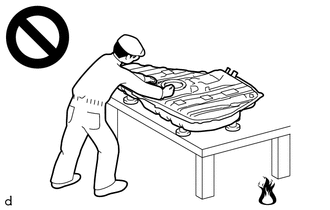
Never perform work on fuel system components near any possible ignition sources.
-
Vaporized fuel could ignite, resulting in a serious accident.
-
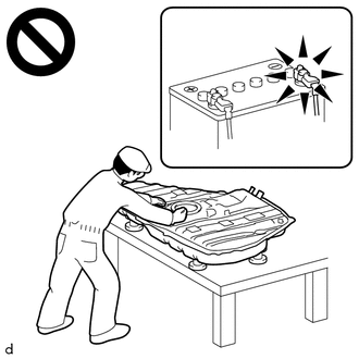
Do not perform work on fuel system components without first disconnecting the cable from the negative (-) battery terminal.
-
Sparks could cause vaporized fuel to ignite, resulting in a serious accident.
PROCEDURE
-
PRECAUTION
Note
After turning the engine switch off, waiting time may be required before disconnecting the cable from the negative (-) battery terminal. Therefore, make sure to read the disconnecting the cable from the negative (-) battery terminal notices before proceeding with work.
-
DISCHARGE FUEL SYSTEM PRESSURE
-
DISCONNECT CABLE FROM NEGATIVE BATTERY TERMINAL
Note
When disconnecting the cable, some systems need to be initialized after the cable is reconnected.
-
REMOVE INTAKE MANIFOLD
-
REMOVE NO. 1 FUEL PIPE SUB-ASSEMBLY
-
DISCONNECT NO. 5 ENGINE WIRE
-
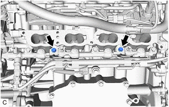
Remove the 2 bolts and disconnect the No. 5 engine wire from the fuel delivery pipe sub-assembly.
-
Disconnect the 4 direct fuel injector assembly connectors.
-
Disconnect the fuel pressure sensor connector.
-
-
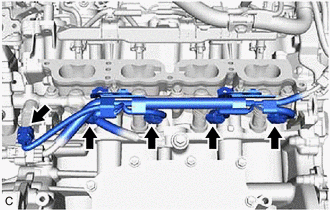
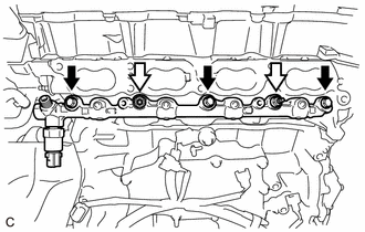
REMOVE FUEL DELIVERY PIPE SUB-ASSEMBLY
-

Bolt 
Nut Remove the 3 bolts, 2 nuts and fuel delivery pipe sub-assembly with the direct fuel injector assemblies.
Note
-
Make sure not to touch or strike the tips of the direct fuel injector assemblies.
-
Pull and remove the fuel delivery pipe sub-assembly in a straight line without tilting it.
-
-
-
REMOVE DIRECT FUEL INJECTOR ASSEMBLY
-
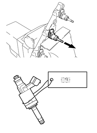
*1 NO. 2 Secure the fuel delivery pipe sub-assembly in a vise between aluminum plates and pull out the 4 direct fuel injector assemblies.
Note
-
Pull and remove each direct fuel injector assembly in a straight line to avoid damaging the seal surface of the fuel delivery pipe sub-assembly O-ring.
-
For reinstallation, attach a tag or label with the corresponding cylinder number to each direct fuel injector assembly.
-
-
Remove the nozzle holder clamp from each direct fuel injector assembly.
-
Using needle nose pliers, remove the No. 3 fuel injector back-up ring from each direct fuel injector assembly.
-
Remove the O-ring and No. 1 fuel injector back-up ring from each direct fuel injector assembly.
-
Remove the C-ring and injector vibration insulator from each direct fuel injector assembly.
-
-
REMOVE FUEL INJECTOR SEAL
-

Using the tip of needle nose pliers, pinch and pull the fuel injector seal at several points to stretch it.
Note
-
Excessively pinching the fuel injector seal may damage the groove of the direct fuel injector assembly.
-
If a direct fuel injector assembly is dropped or the tip of a direct fuel injector assembly is struck, replace it with a new one.
-
-
Remove the fuel injector seal from each direct fuel injector assembly.
-