FRONT LOWER SUSPENSION ARM INSTALLATION
CAUTION / NOTICE / HINT
Use the same procedure for the RH side and LH side.
The following procedure is for the LH side.
PROCEDURE
TEMPORARILY INSTALL FRONT LOWER NO. 1 SUSPENSION ARM SUB-ASSEMBLY
Temporarily install the front lower No. 1 suspension arm sub-assembly to the front suspension crossmember sub-assembly with the 2 bolts.
CONNECT FRONT LOWER NO. 1 SUSPENSION ARM SUB-ASSEMBLY
Connect the front lower No. 1 suspension arm sub-assembly to the steering knuckle with the nut.
98 N*m
999 kgf*cm
72 ft.*lbf
Note:Prevent oil from adhering to the threaded and tapered parts.
Install a new clip.
Note:Further tighten the nut up to 60° if the holes for the clip are not aligned.
INSTALL FRONT STABILIZER BOLT
-
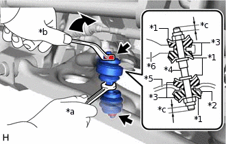
*1
No. 1 Cushion Retainer
*2
No. 2 Cushion Retainer
*3
Front Stabilizer Cushion
*4
Front Stabilizer Bolt
*5
Front Lower No. 1 Suspension Arm Sub-assembly
*6
Front Stabilizer Bar
*a
Hold
*b
Turn
*c
4.0 mm (0.157 in.) or more
Install the 4 No. 1 cushion retainers, 4 front stabilizer cushions, No. 2 cushion retainer and front stabilizer bolt as shown in the illustration, and temporarily install 2 new nuts.
Note:Make sure to install the 4 front stabilizer cushions so that the protrusion of each front stabilizer cushion is inserted into the hole of either the front stabilizer bar or front lower No. 1 suspension arm sub-assembly.
While holding the front stabilizer bolt using a wrench, tighten the 2 nuts.
18 N*m
184 kgf*cm
13 ft.*lbf
-
INSTALL FRONT WHEEL
STABILIZE SUSPENSION
FULLY TIGHTEN FRONT LOWER NO. 1 SUSPENSION ARM SUB-ASSEMBLY
-
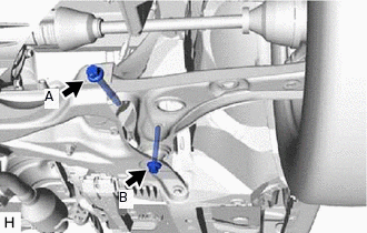
Fully tighten the 2 bolts.
Bolt (A)
128 N*m
1305 kgf*cm
94 ft.*lbf
Bolt (B)
134 N*m
1366 kgf*cm
99 ft.*lbf
-
INSPECT AND ADJUST FRONT WHEEL ALIGNMENT