LOWER INSTRUMENT PANEL INSTALLATION
CAUTION / NOTICE / HINT
Use the same procedure for RHD and LHD vehicles.
The procedure listed below is for LHD vehicles.
A bolt without a torque specification is shown in the standard bolt chart.
PROCEDURE
INSTALL LOWER INSTRUMENT PANEL
Cut off both ends at the positions shown in the illustration (runner) (when installing new part).
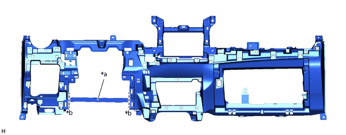
*a
Runner
*b
Cut-off Line
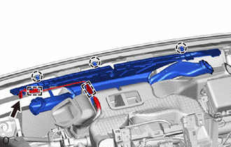
Install the lower instrument panel with the 7 bolts <E> or <F>, 2 bolts <C> or <D> and bolt <G>.
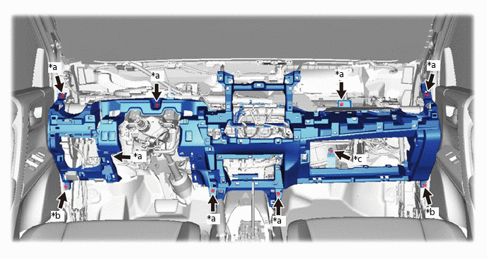
*a
Bolt <E> or <F>
*b
Bolt <C> or <D>
*c
Bolt <G>
-
-
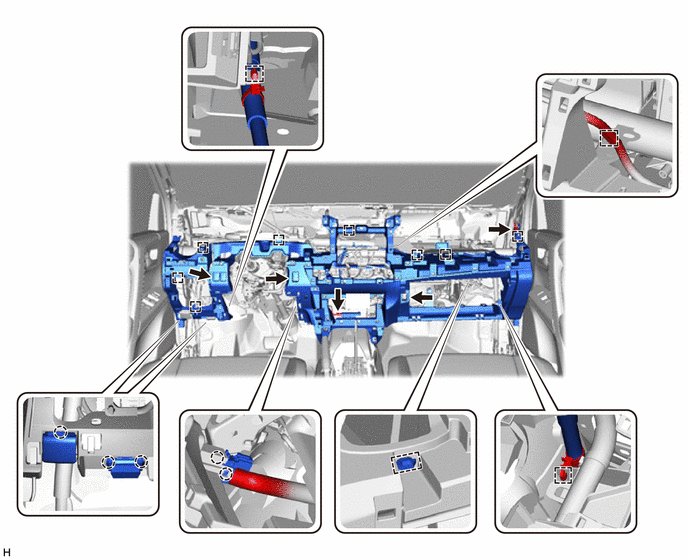
Attach the 2 claws to connect the cooler thermistor.
Attach the 2 claws to connect the DLC3.
Attach the claw to connect the hood lock control lever.
Connect the connectors and attach the clamps.
INSTALL HEATER TO REGISTER DUCT ASSEMBLY
-
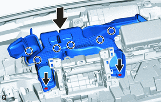
Lower the heater to register duct assembly to attach the 6 claws and install it.
Install the 2 clips.
-
INSTALL DEFROSTER NOZZLE ASSEMBLY
-
Attach the 3 claws to install the defroster nozzle assembly.
Attach the 2 wire harness clamps and connect the connector.
-
INSTALL COWL SIDE TRIM BOARD LH
-
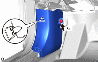
*a
Cap Nut
Attach the clip to install the cowl side trim board LH.
Install the cap nut.
-
INSTALL COWL SIDE TRIM BOARD RH
Tip:Use the same procedure described for the LH side.
INSTALL FRONT DOOR SCUFF PLATE LH
INSTALL FRONT DOOR SCUFF PLATE RH
INSTALL NO. 2 INSTRUMENT PANEL UNDER COVER SUB-ASSEMBLY
-
Attach the 2 guides and 2 claws to install the No. 2 instrument panel under cover sub-assembly.
-
INSTALL LOWER NO. 1 INSTRUMENT PANEL AIRBAG ASSEMBLY
INSTALL FUSE BOX OPENING COVER
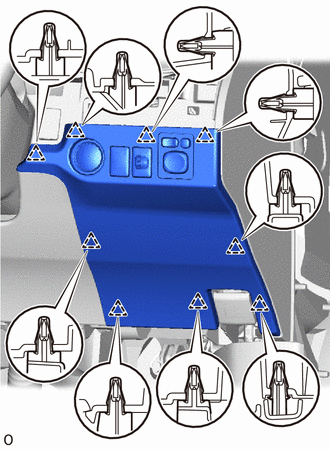
for LHD:
-
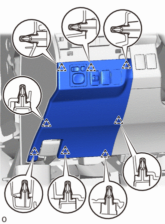
Connect the connectors and attach the clamps.
Attach the 8 clips to install the fuse box opening cover.
-
for RHD:
-
Connect the connectors.
Attach the 9 clips to install the fuse box opening cover.
-
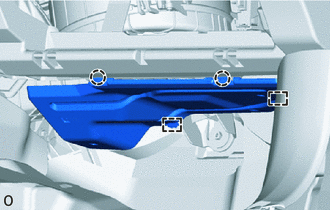
INSTALL NO. 1 INSTRUMENT PANEL UNDER COVER SUB-ASSEMBLY
-
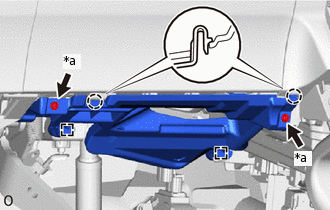
*a
Screw <A> or Screw <B>
Connect the connector.
Attach the 2 guides and 2 claws to install the No. 1 instrument panel under cover sub-assembly.
Install the 2 screws <A> or <B>.
-
INSTALL LOWER NO. 2 INSTRUMENT PANEL FINISH PANEL
-
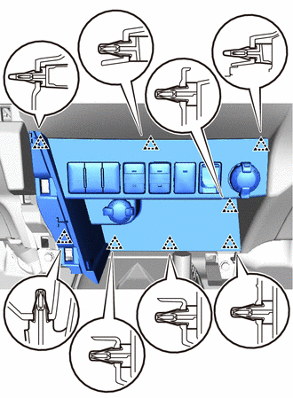
Connect the connectors.
Attach the 8 clips to install the lower No. 2 instrument panel finish panel.
-
INSTALL REAR CONSOLE BOX SUB-ASSEMBLY
INSTALL UPPER INSTRUMENT PANEL
CONNECT CABLE TO NEGATIVE AUXILIARY BATTERY TERMINAL
Note:When disconnecting the cable, some systems need to be initialized after the cable is reconnected.
CHECK SRS WARNING LIGHT
INSTALL DECK BOARD ASSEMBLY