SMART ENTRY AND START SYSTEM(for Start Function) Security Indicator Light Does not Blink
DESCRIPTION
-
The certification ECU (smart key ECU assembly) blinks the security indicator light (telltale light assembly)*1 or security indicator light (clock assembly)*2 when the immobiliser is set (engine switch off).
-
The certification ECU (smart key ECU assembly) receives the security indicator light signal from the main body ECU (multiplex network body ECU) via CAN communication when the theft deterrent system is in the arming preparation state or alarm sounding state. Then, the certification ECU (smart key ECU assembly) blinks the security indicator light (telltale light assembly)*1 or security indicator light (clock assembly)*2.
-
*1: w/ Telltale Light Assembly
-
*2: w/ Clock Assembly
WIRING DIAGRAM
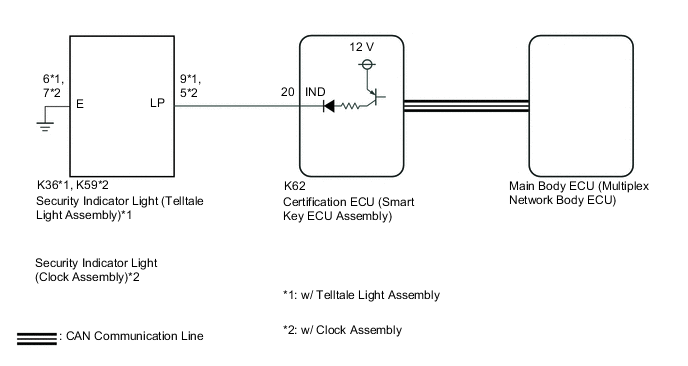
CAUTION / NOTICE / HINT
Note
-
When using the GTS with the engine switch off, connect the GTS to the DLC3 and turn a courtesy light switch on and off at intervals of 1.5 seconds or less until communication between the GTS and the vehicle begins. Then select Model Code "KEY REGIST" under manual mode and enter the following menus: Body Electrical / Entry&Start(CAN). While using the GTS, periodically turn a courtesy light switch on and off at intervals of 1.5 seconds or less to maintain communication between the GTS and the vehicle.
-
The smart entry and start system (for Start Function) uses the LIN communication system and CAN communication system. Inspect the communication function by following How to Proceed with Troubleshooting. Troubleshoot the smart entry and start system (for Start Function) after confirming that the communication systems are functioning properly.
-
Before replacing the certification ECU (smart key ECU assembly) or main body ECU (multiplex network body ECU), refer to Service Bulletin.
-
The vehicle battery supplies power to the main body ECU (multiplex network body ECU) via the door control battery. Therefore, before performing this troubleshooting procedure, make sure to perform an on-vehicle inspection to confirm that the main body ECU (multiplex network body ECU) power source circuit is normal.*
-
*: w/ Door Control Battery
PROCEDURE
-
CHECK FOR DTC
-
Check for DTCs.
Body Electrical > Entry&Start > Trouble Codes
Powertrain > Engine > Trouble Codes
Powertrain > Engine and ECT > Trouble CodesOK DTCs are not output. Result Proceed to OK NG
NG 
GO TO DIAGNOSTIC TROUBLE CODE CHART Click here
OK 
-
-
PERFORM ACTIVE TEST USING GTS (IMMOBILISER INDICATOR)
-
Connect the GTS to the DLC3.
-
Turn the engine switch on (IG).
-
Turn the GTS on.
-
Enter the following menus: Body Electrical / Entry&Start / Active Test.
-
Perform the Active Test according to the display on the GTS.
Body Electrical > Entry&Start > Active TestTester Display Measurement Item Control Range Diagnostic Note Immobiliser Indicator Security indicator light OFF/ON -
Body Electrical > Entry&Start > Active TestTester Display Immobiliser Indicator OK The security indicator light operates normally. Result Proceed to OK NG
NG 
CHECK HARNESS AND CONNECTOR (CERTIFICATION ECU (SMART KEY ECU ASSEMBLY) - SECURITY INDICATOR LIGHT AND BODY GROUND) Click here
OK
-
-
CHECK SECURITY INDICATOR LIGHT OPERATION
-
When the immobiliser is set, check that the security indicator light blinks.*1
OK The security indicator light blinks normally. -
When the theft deterrent system is in the arming preparation state, check that the security indicator light illuminates.*2
OK The security indicator light illuminates normally. Result Result Proceed to *1 is NG (*2 is OK) A *2 is NG (*1 is OK) B
A
REPLACE CERTIFICATION ECU (SMART KEY ECU ASSEMBLY)
B
REPLACE MAIN BODY ECU (MULTIPLEX NETWORK BODY ECU) Click here
-
-
CHECK HARNESS AND CONNECTOR (CERTIFICATION ECU (SMART KEY ECU ASSEMBLY) - SECURITY INDICATOR LIGHT AND BODY GROUND)
-
Disconnect the K62 certification ECU (smart key ECU assembly) connector.
-
Disconnect the K36 security indicator light (telltale light assembly) connector.*1
-
Disconnect the K59 security indicator light (clock assembly) connector.*2
-
*1: w/ Telltale Light Assembly
-
*2: w/ Clock Assembly
-
-
Measure the resistance according to the value(s) in the table below.
Standard Resistance w/ Telltale Light Assembly Tester Connection Condition Specified Condition K62-20 (IND) - K36-9 (LP) Always Below 1 Ω K62-20 (IND) or K36-9 (LP) - Other terminals and body ground Always 10 kΩ or higher K36-6 (E) - Body ground Always Below 1 Ω w/ Clock Assembly Tester Connection Condition Specified Condition K62-20 (IND) - K59-5 (LP) Always Below 1 Ω K62-20 (IND) or K59-5 (LP) - Other terminals and body ground Always 10 kΩ or higher K59-7 (E) - Body ground Always Below 1 Ω Result Proceed to OK NG
NG
REPAIR OR REPLACE HARNESS OR CONNECTOR
OK
-
-
CHECK CERTIFICATION ECU (SMART KEY ECU ASSEMBLY)
-
Connect the K62 certification ECU (smart key ECU assembly) connector.
-
Connect the K36 security indicator light (telltale light assembly) connector.*1
-
Connect the K59 security indicator light (clock assembly) connector.*2
-
*1: w/ Telltale Light Assembly
-
*2: w/ Clock Assembly
-
-
Using an oscilloscope, check the waveform.
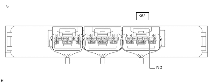
*a Component with harness connected
(Certification ECU (Smart Key ECU Assembly))
- - Measurement Condition Tester Connection Condition Specified Condition K62-20 (IND) - Body ground Engine switch off → on (IG) Pulse generation → Below 2 V Result Result Proceed to OK (w/ Telltale Light Assembly) A OK (w/ Clock Assembly) B NG C
A
REPLACE SECURITY INDICATOR LIGHT (TELLTALE LIGHT ASSEMBLY) Click here
B
REPLACE SECURITY INDICATOR LIGHT (CLOCK ASSEMBLY) Click here
C
REPLACE CERTIFICATION ECU (SMART KEY ECU ASSEMBLY)
-