SFI SYSTEM FREEZE FRAME DATA
DESCRIPTION
The ECM records vehicle and driving condition information as freeze frame data the moment a DTC is stored. When troubleshooting, freeze frame data can be helpful in determining whether the vehicle was moving or stationary, whether the engine was warmed up or not, whether the air fuel ratio was lean or rich, as well as other data recorded at the time of a malfunction.
Tip:If it is impossible to replicate the problem even though a DTC is detected, confirm the freeze frame data.
Freeze frame data is available in long and short forms.
PENDING FREEZE FRAME DATA
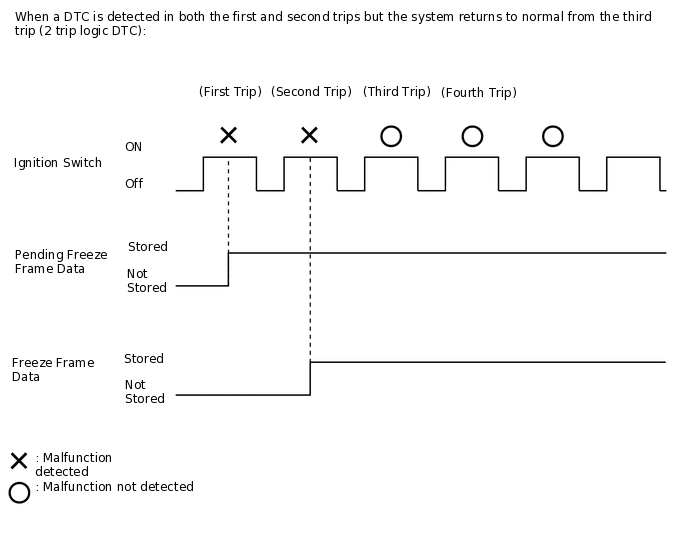
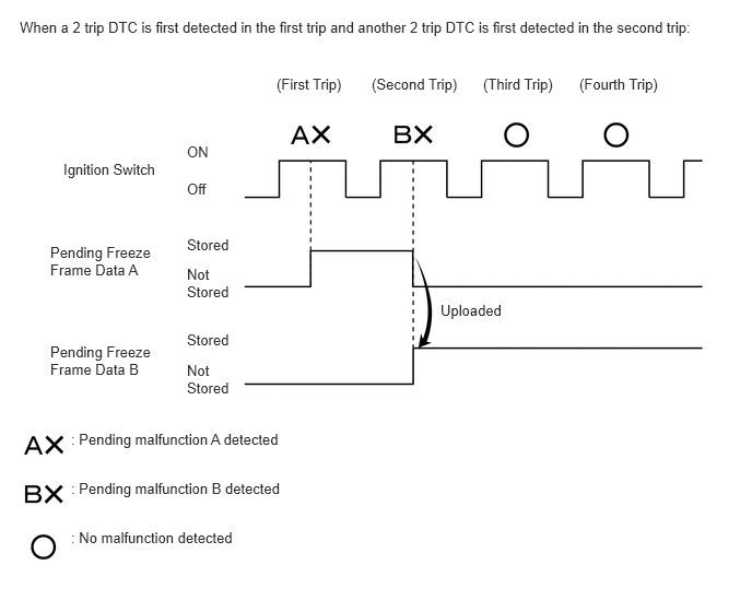
Tip:Pending freeze frame data is stored when a 2 trip DTC is first detected during the first trip.
Connect the GTS to the DLC3.
Turn the ignition switch to ON.
Turn the GTS on.
Enter the following menus: Powertrain / Engine / Trouble Codes.
Select a DTC in order to display its pending freeze frame data.
Powertrain > Engine > Trouble Codes
Tip:Pending freeze frame data is cleared when any of the following occurs.
-
DTCs cleared using the GTS.
-
The cable is disconnected from the negative (-) battery terminal.
-
40 trips with the engine fully warmed up have been performed after returning to normal. (Pending freeze frame data will not be cleared by only returning the system to normal.)
With previous pending freeze frame data stored, if pending freeze frame data is newly stored when a 2 trip DTC is detected in the first trip, the old freeze frame data will be replaced with the new data of the newly detected DTC in the next trip.
LIST OF FREEZE FRAME DATA
Powertrain > Engine
Tester Display
Vehicle Speed
Engine Speed
Calculate Load
Vehicle Load
Mass Air Flow Sensor
Atmospheric Pressure
Engine Oil Temperature Sensor
Coolant Temperature
Intake Air Temperature
Intake Air Temperature B1S1 (Turbo)
Engine Run Time
IG-ON Coolant Temperature
Initial Engine Coolant Temperature
IG-ON Intake Air Temperature
Initial Engine Intake Air Temperature
Battery Voltage
Battery Sensor Voltage
BATT Voltage
Engine Oil Pressure
Accelerator Position
Accelerator Position Sensor No.1 Voltage %
Accelerator Position Sensor No.2 Voltage %
Accelerator Position Sensor No.1 Voltage
Accelerator Position Sensor No.2 Voltage
Accelerator Position Sensor No.1 Fully Closed Learn Value
Accelerator Position Sensor No.2 Fully Closed Learn Value
Engine Starting Torque Control Count
Throttle Position Sensor No.1 Voltage %
Throttle Position Sensor No.2 Voltage %
System Guard
Open Side Malfunction
Throttle Request Position
Throttle Sensor Position
Throttle Position Sensor No.1 Voltage
Throttle Position Sensor No.2 Voltage
Throttle Position Command
Throttle Position Sensor Open Position No.1
Throttle Position Sensor Open Position No.2
Throttle Motor Current
Throttle Motor Duty Ratio
Throttle Motor Duty Ratio (Open)
Throttle Motor Duty Ratio (Close)
Throttle Position Sensor Fully Closed Learn Value
+BM Voltage
Actuator Power Supply
Throttle Air Flow Learn Value (Area 1)
Throttle Air Flow Learn Value (Area 2)
Throttle Air Flow Learn Value (Area 3)
Throttle Air Flow Learn Value (Calculated Value)
Throttle Air Flow Learn Value (Atmosphere Pressure Offset Value)
Wastegate Valve Control Duty Ratio
Low Revolution Control
Neutral Control
N Range Status
Engine Stall Control F/B Flow
ISC F/B Learn Torque
ISC Total AUXS Torque
ISC F/B Torque
Sum of ISC F/B Torque (Recent)
ISC AUXS Torque (Alternator)
ISC AUXS Torque (Air Conditioner)
Throttle Air Flow F/B Value
Throttle Position
Target Fuel Pressure (High)
Target Fuel Pressure (Low)
Fuel Pressure (High)
Fuel Pressure (Low)
Fuel Pump Control Duty Ratio
Injection Volume Cylinder #1
Target Fuel Pressure Offset
Injection Volume
High Fuel Pressure Sensor
High Pressure Fuel Pump Duty Ratio (D4)
High Pressure Fuel Pump Discharge Rate
Injection Timing Cylinder #1 (D4)
Injection Time Cylinder #1 (D4)
Current Fuel Type
EVAP (Purge) VSV
Target Air-Fuel Ratio
A/F (O2) Lambda Sensor B1S1
A/F (O2) Sensor Voltage B1S1
A/F (O2) Sensor Current B1S1
A/F (O2) Sensor Heater Duty Ratio B1S1
O2 Sensor Voltage B1S2
O2 Sensor Impedance B1S2
O2 Sensor Heater B1S2
O2 Sensor Heater Current Value B1S2
Short FT Bank 1
Long FT Bank 1
Total FT Bank 1
Fuel System Status Bank 1
Fuel System Status Bank 2
Ignition Timing Cylinder #1
Knock F/B Value
Knock Correct Learn Value
Idle Spark Advance Control Cylinder #1
Idle Spark Advance Control Cylinder #2
Idle Spark Advance Control Cylinder #3
Idle Spark Advance Control Cylinder #4
Intercooler Water Pump Speed
Intercooler Water Pump
Mass Air Flow Circuit
VVT Advance Fail
Intake VVT Hold Correct Learn Value Bank 1 (Area 1)
Intake VVT Hold Correct Learn Value Bank 1 (Area 2)
Intake VVT Change Angle Bank 1
Intake VVT OCV Control Duty Ratio Bank 1
Exhaust VVT Hold Learn Value Bank 1
Exhaust VVT Change Angle Bank 1
Exhaust VVT OCV Control Duty Ratio Bank 1
Intake VVT Target Angle Bank 1
Exhaust VVT Target Angle Bank 1
Target Boost Pressure
Boost Pressure Sensor
Catalyst Temperature B1S1
Catalyst Temperature B1S2
Starter SW
Neutral Position SW
Clutch SW
Stop Light SW
Immobiliser Communication
Cruise Main SW
TC Terminal
MIL ON Run Distance
Running Time from MIL ON
Time after DTC Cleared
Distance from DTC Cleared
Warmup Cycle Cleared DTC
Distance Traveled from Last Battery Cable Disconnect
IG OFF Elapsed Time
Total Distance Traveled
Ignition Trigger Count
Misfire Count Cylinder #1
Misfire Count Cylinder #2
Misfire Count Cylinder #3
Misfire Count Cylinder #4
All Cylinders Misfire Count
Misfire RPM
Misfire Load
Misfire Margin
Catalyst OT Misfire Fuel Cut
Catalyst OT Misfire Fuel Cut History
Catalyst OT Misfire Fuel Cut Cylinder #1
Catalyst OT Misfire Fuel Cut Cylinder #2
Catalyst OT Misfire Fuel Cut Cylinder #3
Catalyst OT Misfire Fuel Cut Cylinder #4
Engine Speed (Starter Off)
Starter Count
Run Distance of Previous Trip
Engine Starting Time
Engine Start Hesitation
Low Revolution for Engine Start
Fuel Cut Elapsed Time
Previous Trip Coolant Temp
Previous Trip Intake Temp
Engine Oil Temperature
Previous Trip Eng Oil Temp
Ambient Temp for A/C
Previous Trip Ambient Temp
A/F Learn Value Idle Bank 1
A/F Learn Value Low Bank 1
A/F Learn Value Mid No.1 Bank 1
A/F Learn Value Mid No.2 Bank 1
A/F Learn Value High Bank 1
A/F Learn Value Low (Dual) Bank 1
A/F Learn Value Mid (Dual) No.1 Bank 1
A/F Learn Value Mid (Dual) No.2 Bank 1
A/F Learn Value High (Dual) Bank 1
Compression Leakage Count
Rough Idle Status
Plural Cylinders Rough Idle
Rough Idle Cylinder #1
Rough Idle Cylinder #2
Rough Idle Cylinder #3
Rough Idle Cylinder #4
Cooling Fan Duty Ratio
Brake Override System
Immobiliser Fuel Cut Status
Immobiliser Fuel Cut History
Key Unlock Signal
Engine Speed Cylinder #1
Engine Speed Cylinder #2
Engine Speed Cylinder #3
Engine Speed Cylinder #4
Average Engine Speed of All Cylinder
Received MIL from ECT
Output Axis Speed
NT Sensor Speed
Shift SW Status (P Range)
Shift SW Status (R Range)
Shift SW Status (N Range)
Shift SW Status (N,P Range)
Sport Shift Up SW
Sport Shift Down SW
Shift SW Status (S Range)
Shift SW Status (D Range)
A/T Oil Temperature No.1
Drive Mode Status
Power Mode SW
Acceleration Sensor Voltage
Lock Up Status
Shift Range Indicator
Down Shift Indication
Up Shift Indication
Acceleration Sensor Calibration
Acceleration Sensor Learn Value
Stop and Start System Engine Status
Air Bypass Valve Control