EMISSION CONTROL SYSTEM (w/ Secondary Air Injection System) SYSTEM DIAGRAM
-
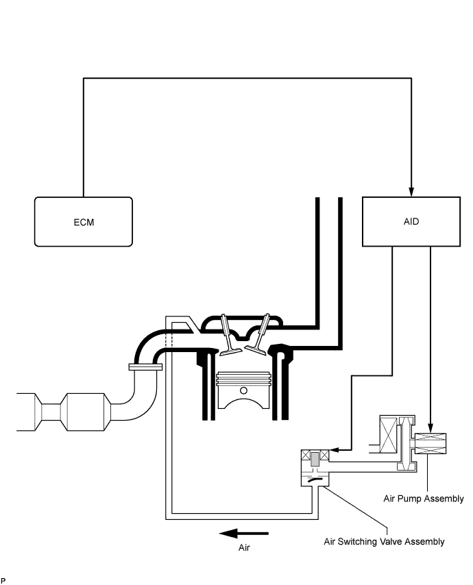
SECONDARY AIR INJECTION SYSTEM ILLUSTRATION
During a cold engine start, this system purifies the catalyst exhaust fumes by applying air pressure to the air hose, exhaust manifold and cylinder head exhaust port.
-
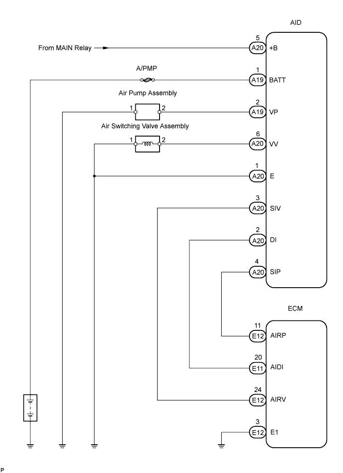
SECONDARY AIR INJECTION SYSTEM WIRING DIAGRAM
-
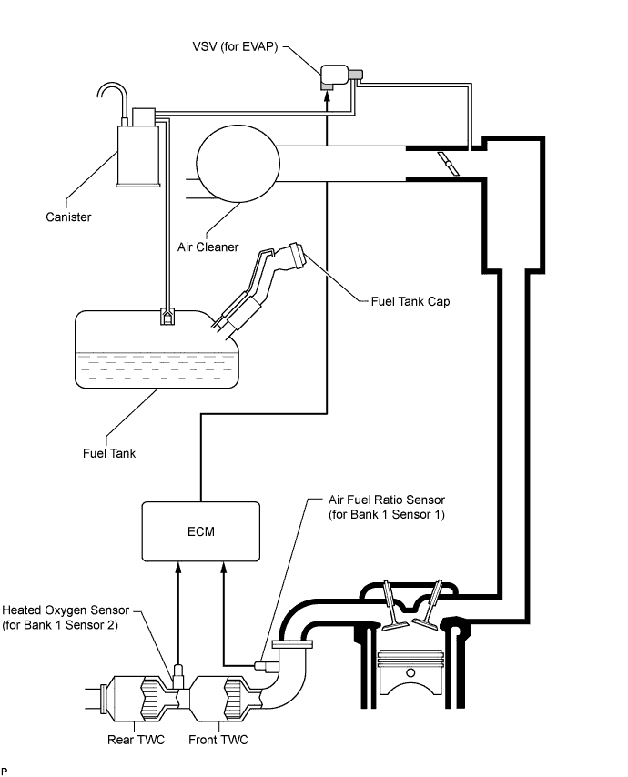
EMISSION CONTROL AND EVAP CONTROL SYSTEM ILLUSTRATION
To reduce HC emissions, the following occurs. First, evaporated fuel in the fuel tank is absorbed by the canister's active carbon. Then, when the vehicle is being driven, the fuel in the canister and air are routed into the intake manifold for combustion.
-
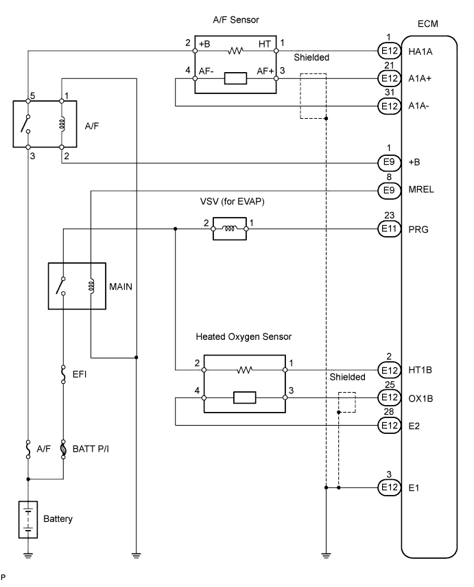
EMISSION CONTROL AND EVAP CONTROL WIRING DIAGRAM