PARKING BRAKE SYSTEM ADJUSTMENT
-
CHECK PARKING BRAKE LEVER TRAVEL
-
Pull the parking brake lever to fully engage the parking brake.
-
Release the lever to disengage the parking brake.
-
Slowly pull the parking brake lever all the way, and count the number of clicks.
Standard parking brake lever travel when pulled with a force of 200 N (20 kgf, 45 lbf) 6 to 8 clicks (for 2WD) 7 to 9 clicks (for 4WD and Pre-Runner)
-
-
REMOVE UPPER CONSOLE PANEL SUB-ASSEMBLY
-
REMOVE REAR WHEEL
-
ADJUST BRAKE SHOE CLEARANCE (for 2WD)
-
Check that each part is installed properly.
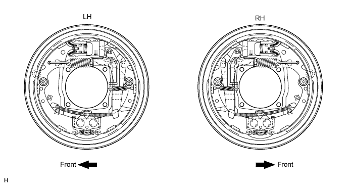
-

Measure the inside diameter of the drum and diameter of the brake shoes. Check that the difference between the diameters is the correct shoe clearance.
Standard shoe clearance 0.5 mm (0.0197 in.) Note
There should be no oil or grease on the contact surfaces of the shoe lining and drum.
-
-
ADJUST BRAKE SHOE CLEARANCE (for 4WD and Pre-Runner)
-
Check that each part is installed properly.
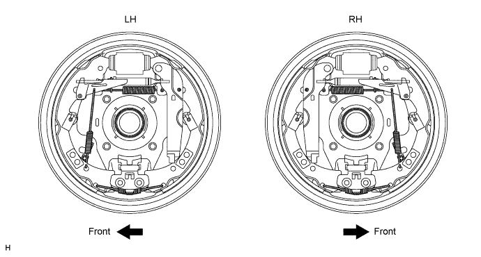
-
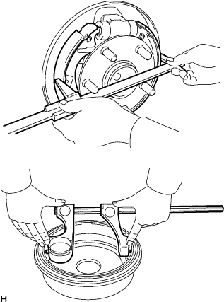
Measure the inside diameter of the drum and the diameter of the shoes. Check that the difference between the diameters is the correct shoe clearance.
Standard shoe clearance 0.6 mm (0.0236 in.) Note
There should be no oil or grease on the contact surfaces of the shoe lining and drum.
-
-
ADJUST PARKING BRAKE LEVER TRAVEL
-
Completely release the parking brake lever.
-
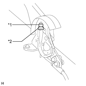
Text in Illustration *1 Lock Nut *2 No. 1 Parking Brake Cable Adjusting Nut Loosen the lock nut.
-
Turn the No. 1 parking brake cable adjusting nut until the lever travel is correct.
-
Tighten the lock nut.
- Torque:
- 5.2 N*m { 53 kgf*cm, 46 in.*lbf }
Tech Tips
If the lever travel cannot be fully adjusted with this procedure, proceed to the Adjust Parking Brake Turn Buckle procedure.
-
-
ADJUST PARKING BRAKE TURN BUCKLE
-
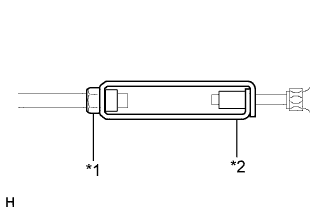
Text in Illustration *1 Lock Nut *2 Turn Buckle Loosen the lock nut and turn the buckle until the lever travel is correct.
-
Tighten the lock nut.
- Torque:
- 5.0 N*m { 51 kgf*cm, 44 in.*lbf }
-
-
INSPECT BRAKE WARNING LIGHT
-
Operate the parking brake lever and check the illumination condition of the brake warning light.
OK The brake warning light always illuminates at the first click.
-
-
INSTALL UPPER CONSOLE PANEL SUB-ASSEMBLY
-
INSTALL REAR WHEEL (for 2WD)
-
Install the wheel.
- Torque:
- 152 N*m { 1,550 kgf*cm, 112 ft.*lbf, for steel wheel }
- 121 N*m { 1,234 kgf*cm, 89 ft.*lbf, for aluminum wheel }
-
-
INSTALL REAR WHEEL (for 4WD and Pre-Runner)
-
Install the wheel.
- Torque:
- 105 N*m { 1,070 kgf*cm, 77 ft.*lbf }
-