FIT STANDARD / ADJUSTMENT METHOD ADJUSTMENT
-
INSPECT HOOD SUB-ASSEMBLY
-
Check that the clearance measurements of areas a through f are within each standard range.
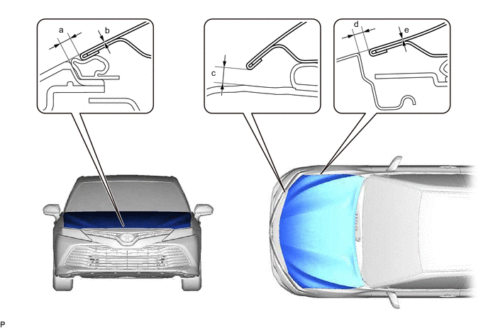
Standard Clearance Area Measurement Area Measurement a 2.8 to 6.8 mm (0.110 to 0.268 in.) b -2 to 2 mm (-0.0787 to 0.0787 in.) c 5.9 to 9.9 mm (0.232 to 0.390 in.) d 2.5 to 5.5 mm (0.0984 to 0.217 in.) e -1.5 to 1.5 mm (-0.0591 to 0.0591 in.) - -
Tech Tips
Centering bolts are used to install the hood hinges and hood lock. The hood and hood lock cannot be adjusted with the centering bolts installed. Substitute the centering bolts with standard bolts with washers when making adjustments.
-
-
ADJUST HOOD SUB-ASSEMBLY
-
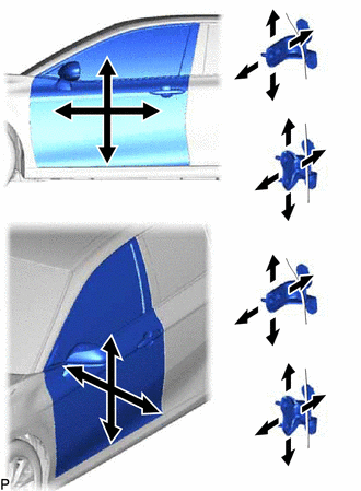
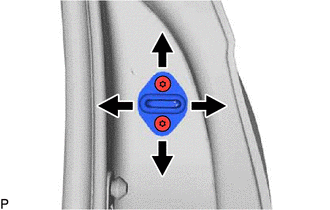
Horizontally and vertically adjust the hood.
-
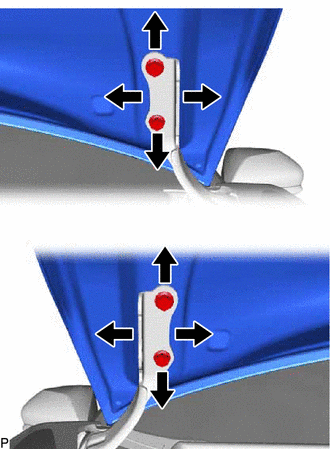
Loosen the 4 hinge bolts of the hood.
-
Adjust the clearance between the hood and front fenders by moving the hood.
-
Tighten the 4 hinge bolts after adjustment.
- Torque:
- 13 N*m { 133 kgf*cm, 10 ft.*lbf }
-
-
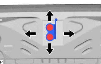
Adjust the height of the front end of the hood using the hood bumper cushions.
-
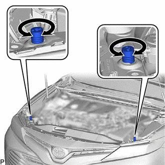
Adjust the 2 hood bumper cushions so that the heights of the hood and fenders are aligned.
Tech Tips
Raise or lower the front end of the hood by turning the 2 hood bumper cushions.
-
-
Adjust the hood lock.
-
Remove the radiator support opening cover.
-
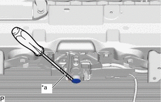
*a Protective Tape Using a screwdriver with its tip wrapped with protective tape, remove the hood lock nut cap.
-
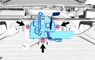
*1 Hood Lock Bolt Loosen the 2 bolts and hood lock bolt.
-
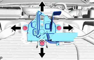
Adjust the hood lock assembly and tighten the 2 bolts and hood lock bolt.
- Torque:
- 7.5 N*m { 76 kgf*cm, 66 in.*lbf }
-
Check that the striker can engage the hood lock assembly smoothly.
-
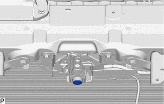
Install a new hood lock nut cap.
-
Install the radiator support opening cover.
-
-
-
INSPECT FRONT DOOR
-
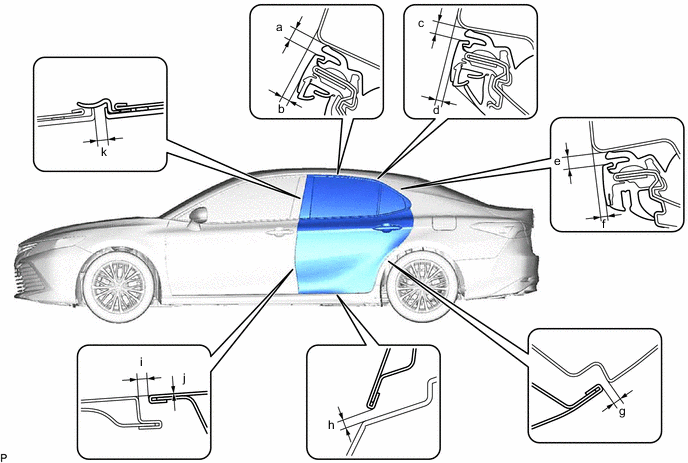
Check that the clearance measurements of areas a through n are within each standard range.
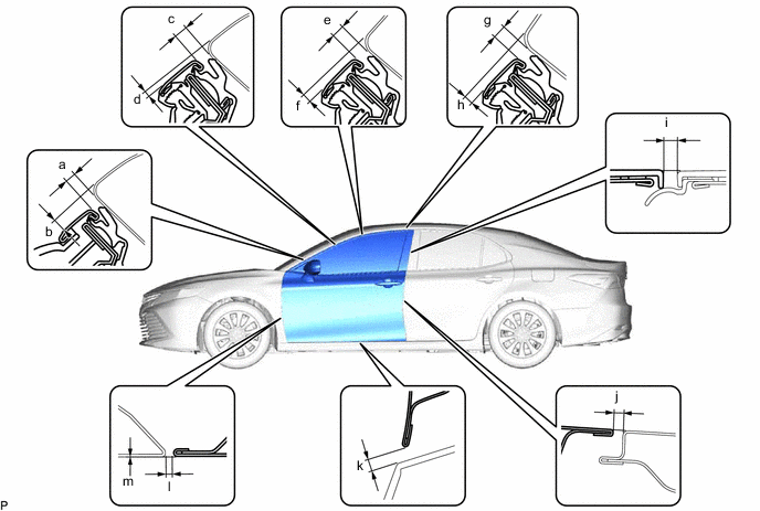
Standard Clearance Area Measurement Area Measurement a 3.3 to 6.7 mm (0.130 to 0.264 in.) b 3.5 to 7.5 mm (0.138 to 0.295 in.) c 3.3 to 6.7 mm (0.130 to 0.264 in.) d 0.2 to 4.2 mm (0.0079 to 0.165 in.) e 3.3 to 6.7 mm (0.130 to 0.264 in.) f 1.2 to 5.2 mm (0.0472 to 0.205 in.) g 3.3 to 6.7 mm (0.130 to 0.264 in.) h 1.1 to 5.1 mm (0.0433 to 0.201 in.) i 2.3 to 6.3 mm (0.0906 to 0.248 in.) j 4.1 mm (0.161 in.) k 5.3 mm (0.209 in.) l 2.6 to 5.0 mm (0.102 to 0.197 in.) m -1.2 to 1.2 mm (-0.0472 to 0.0472 in.) - -
Tech Tips
-
Use the same procedure for the RH side and LH side.
-
The following procedure is for the LH side.
-
Centering bolts are used to install the door hinges to the vehicle body and door. The door cannot be adjusted with the centering bolts installed. Substitute the centering bolts with standard bolts when making adjustments.
-
-
ADJUST FRONT DOOR
Note
Make sure to turn the power switch off before adjusting the door lock strikers.
-
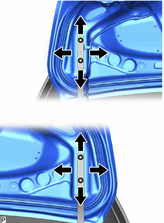
Using SST, loosen the 4 hinge bolts on the vehicle body and adjust the door position.
- SST
- 09812-00020
-
Tighten the 4 hinge bolts on the vehicle body after adjustment.
- Torque:
- 26 N*m { 265 kgf*cm, 19 ft.*lbf }
-
Loosen the 4 hinge bolts on the door and adjust the door position.
-
Tighten the 4 hinge bolts on the door after adjustment.
- Torque:
- 26 N*m { 265 kgf*cm, 19 ft.*lbf }
-
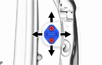
Using a T40 "TORX" socket wrench, slightly loosen the 2 striker mounting screws.
-
Using a brass bar and a hammer, hit the striker to adjust its position.
-
Using a T40 "TORX" socket wrench, tighten the 2 striker mounting screws after adjustment.
- Torque:
- 23 N*m { 235 kgf*cm, 17 ft.*lbf }
-
-
INSPECT REAR DOOR
-
Check that the clearance measurements of areas a through o are within each standard range.
Standard Clearance Area Measurement Area Measurement a 3.3 to 6.7 mm (0.130 to 0.264 in.) b 1.2 to 5.2 mm (0.0472 to 0.205 in.) c 3.3 to 6.7 mm (0.130 to 0.264 in.) d 0.6 to 4.6 mm (0.0236 to 0.181 in.) e 3.3 to 6.7 mm (0.130 to 0.264 in.) f 0.6 to 4.6 mm (0.0236 to 0.181 in.) g 2.3 to 5.3 mm (0.0906 to 0.209 in.) h 5.3 mm (0.209 in.) i 4.1 mm (0.161 in.) j 0 mm (0 in.) k 2.3 to 6.3 mm (0.0906 to 0.248 in.) - -
Tech Tips
-
Use the same procedure for the RH side and LH side.
-
The following procedure is for the LH side.
-
Centering bolts are used to install the door hinges to the vehicle body and door. The door cannot be adjusted with the centering bolts installed. Substitute the centering bolts with standard bolts when making adjustments.
-
-
ADJUST REAR DOOR
Note
Make sure to turn the power switch off before adjusting the door lock strikers.
-
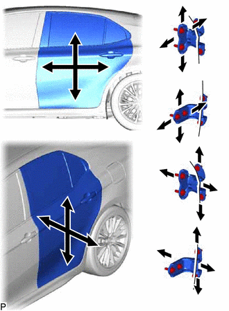
Using SST, loosen the 4 hinge bolts on the vehicle body and adjust the door position.
- SST
- 09812-00020
-
Tighten the 4 hinge bolts on the vehicle body after adjustment.
- Torque:
- 26 N*m { 265 kgf*cm, 19 ft.*lbf }
-
Loosen the 4 hinge bolts on the door and adjust the door position.
-
Tighten the 4 hinge bolts on the door after adjustment.
- Torque:
- 26 N*m { 265 kgf*cm, 19 ft.*lbf }
-
Using a T40 "TORX" socket wrench, slightly loosen the 2 striker mounting screws.
-
Using a brass bar and a hammer, hit the striker to adjust its position.
-
Using a T40 "TORX" socket wrench, tighten the 2 striker mounting screws after adjustment.
- Torque:
- 23 N*m { 235 kgf*cm, 17 ft.*lbf }
-
-
INSPECT BACK DOOR
-
Check that the clearance measurements of areas a through l are within each standard range.
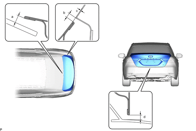
Standard Clearance Area Measurement Area Measurement a 5.8 mm (0.228 in.) b 2.6 to 5.6 mm (0.102 to 0.220 in.) c -1.4 to 1.6 mm (-0.0551 to 0.063 in.) d 4.0 to 8.0 mm (0.157 to 0.315 in.)
Tech Tips
Centering bolts are used to install the door hinges to the door. The door cannot be adjusted with the centering bolts installed. Substitute the centering bolts with standard bolts (with washers) when making adjustments.
-
-
ADJUST LUGGAGE COMPARTMENT DOOR
-
Loosen the 4 door side hinge bolts to adjust the door horizontally and vertically.
-
Tighten the 4 bolts after adjustment.
- Torque:
- 7.5 N*m { 76 kgf*cm, 66 in.*lbf }
-
Using a T40 "TORX" socket wrench, slightly loosen the 2 striker mounting screws.
-
Using a brass bar and a hammer, hit the striker to adjust its position.
-
Using a T40 "TORX" socket wrench, tighten the 2 striker mounting screws after adjustment.
- Torque:
- 23 N*m { 235 kgf*cm, 17 ft.*lbf }
-