METER / GAUGE SYSTEM DETAILS COMBINATION METER
FUNCTION
Buzzer Function
The table below shows the warning and reminder functions of the buzzer in the combination meter assembly.
Priority
Item
1
Pre-crash Safety System Warning*1
2
Shift Position R Indication*2
3
VSC Warning*3
4
Front Seat Belt Warning (Level 2)
5
Rear Seat Belt Warning
6
Front Seat Belt Warning (Level 1)
7
Brake Control System Power Low Warning
8
Brake Fluid Low Warning
9
Engine Switch Operation while Driving Warning*4
10
Restart while Driving Notification*4
11
Pre-crash Safety System Distance Alert*1
12
EPS Warning
13
Speed Limiter Control System Over Speed Warning*5
14
MMT System Warning*2
15
Entry and Start System Warning (Continuous)*4
16
Entry and Start System Warning (Intermittent)*4
17
MMT Active Test or MMT Warning*2
18
Brake System Temperature Rise or Active Test
19
Brake System Temperature Warning
20
Hill-start Assist Control (Level 2) Reset*3
21
Hill-start Assist Control (Level 2) Set*3
22
Hill-start Assist Control (Level 1) Indication*3
23
Hill-start Assist Control (Level 1) Finish*3
24
Entry and Start System Warning (Intermittent, Maximum 9 Times)*4
25
Entry and Start System Warning (Once)*4
26
Lane Departure Alert Warning*1
27
Pre-crash Safety System Malfunction*1
28
Immobiliser Certification Reminder
29
Parking Brake Engaged Warning
30
Door Open while Driving Warning
31
Shift Reject Warning*2
32
Light Reminder
33
Turn Signal/Hazard Warning Operation
34
Low Fuel Warning
*1: Models with pre-crash safety system
*2: Models with multi-mode manual transaxle
*3: Models with vehicle stability control system
*4: Models with entry and start system
*5: Models with speed limiter control system
Multi-information Display
Cruise Information Mode Function
The cruise information on a multi-information display is displayed in the following order each time either of the switch knobs is pressed.
Figure 1. Models with 1KR-FE Engine and Manual Transaxle 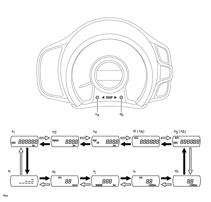
*A
Models with Stop and Start System
-
-
*a
Back Switch Knob
*b
Forward Switch Knob
*c
Odometer
*d
Trip Meter A
*e
Trip Meter B
*f
Stop and Start Operation Time after Engine Start-up
*g
Total Stop and Start Operation Time
*h
Current Fuel Consumption
*i
Total Average Fuel Consumption
*j
Cruising Range
*k
Average Vehicle Speed
*l
Meter Panel Luminance Adjustment Mode
*m
The illustrations shown are examples only.
-
-

Forward switch knob pressed briefly

Back switch knob pressed briefly
Figure 2. Models with 1KR-FE Engine and Multi-mode Manual Transaxle or 1PP Engine 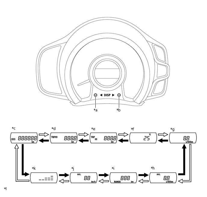
*a
Back Switch Knob
*b
Forward Switch Knob
*c
Odometer
*d
Trip Meter A
*e
Trip Meter B
*f
Outside Temperature
*g
Current Fuel Consumption
*h
Total Average Fuel Consumption
*i
Cruising Range
*j
Average Vehicle Speed
*k
Meter Panel Luminance Adjustment Mode
*l
The illustrations shown are examples only.
Forward switch knob pressed briefly
Back switch knob pressed briefly
Interruption Display Function
Speed Limiter Control System Set Speed (Models with 1KR-FE Engine)
-
When the speed limiter control system is turned on, the action is confirmed by showing the speed limiter control system set speed and symbol in the multi-information display.
Tip:The item shown can return back to the previously shown content by a short push of either of the switch knobs.
Icy Road Condition (Except models with 1KR-FE Engine and Manual Transaxle)
-
When the outside temperature drops below 3°C (37°F), the outside temperature display is shown in the multi-information display and flashes 10 times and then the previously shown screen is displayed again (if the outside temperature display was already shown before the temperature display starts flashing, the screen continues to be displayed).
Tip:The item shown can return back to the previously shown content by a short push of either of the switch knobs.
Stop and Start Operation Time after Engine Start-up (Models with Stop and Start System)
-
When the engine performs an idling stop, the accumulated stop and start operation time after engine start-up is shown in the multi-information display.
Tip:When the idling stop condition is ended, the previously shown screen is displayed again.
The item shown can return back to the previously shown content by a short push of either of the switch knobs.
Customization Function
Stop and Start Operation Time after Engine Start-up (Models with Stop and Start System)
-
Pressing and holding either of the switch knobs for approximately 5 seconds when the stop and start operation time after engine start-up is displayed changes the display to the stop and start operation time after engine start-up interruption display customization display.
Tip:The customization display will change back to the previously shown display after approximately 6 seconds or by pressing either of the switch knobs for approximately 2 seconds.
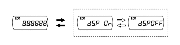
Either of the switch knobs pressed and held
Either of the switch knobs pressed briefly