TELEMATICS SYSTEM(for G-BOOK) Received Voice Signal Circuit
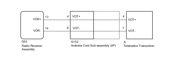
WIRING DIAGRAM
CAUTION / NOTICE / HINT
Note
-
Depending on the parts that are replaced during vehicle inspection or maintenance, performing initialization, registration or calibration may be needed. Refer to Precaution for G-BOOK.
-
When replacing the telematics transceiver, make sure to replace it with a new one.
-
When replacing the radio receiver assembly, always replace it with a new one.
If a radio receiver assembly which was installed to another vehicle is used, the following may occur:
-
A communication malfunction DTC may be stored.
-
The radio receiver assembly may not operate normally.
PROCEDURE
-
CHECK HARNESS AND CONNECTOR (RADIO RECEIVER ASSEMBLY - ANTENNA CORD SUB-ASSEMBLY [I/P])
-
Disconnect the G53 radio receiver assembly connector.
-
Disconnect the G152 antenna cord sub-assembly (I/P) connector.
-
Measure the resistance according to the value(s) in the table below.
Standard Resistance Tester Connection Condition Specified Condition G53-13 (VOR+) - G152-4 (VOT+) Always Below 1 Ω G53-14 (VOR-) - G152-6 (VOT-) Always Below 1 Ω G53-13 (VOR+) - Body ground Always 10 kΩ or higher G53-14 (VOR-) - Body ground Always 10 kΩ or higher Result Proceed to OK NG
NG 
REPAIR OR REPLACE HARNESS OR CONNECTOR
OK 
-
-
CHECK ANTENNA CORD SUB-ASSEMBLY (I/P)
-
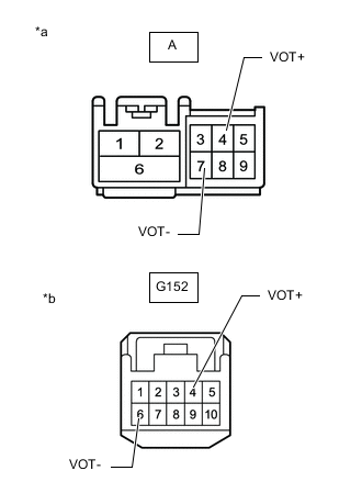
*a Front view of wire harness connector
(to Telematics Transceiver)
*b Front view of wire harness connector
(to Wire Harness)
Disconnect the antenna connector from the telematics transceiver.
-
Disconnect the antenna connector from the wire harness.
-
Measure the resistance according to the value(s) in the table below.
Standard Resistance Tester Connection Condition Specified Condition A-4 (VOT+) - G152-4 (VOT+) Always Below 1 Ω A-7 (VOT-) - G152-6 (VOT-) Always Below 1 Ω A-4 (VOT+) - Body ground Always 10 kΩ or higher A-7 (VOT-) - Body ground Always 10 kΩ or higher Result Proceed to OK NG
NG
REPLACE ANTENNA CORD SUB-ASSEMBLY (I/P) Click here
OK
-
-
CHECK TELEMATICS TRANSCEIVER
-
Remove the telematics transceiver with the connectors still connected.
-
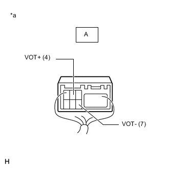
*a Component with harness connected
(Telematics Transceiver)
Check for pulses according to the value(s) in the table below.
Standard Tester Connection Condition Specified Condition A-4 (VOT+) - Body ground Calling while using the operator service A waveform synchronized with the sent voice is output A-7 (VOT-) - Body ground Calling while using the operator service A waveform synchronized with the sent voice is output Result Proceed to OK NG
OK
REPLACE RADIO RECEIVER ASSEMBLY Click here
NG
REPLACE TELEMATICS TRANSCEIVER Click here
-