ENGINE UNIT REPLACEMENT
-
REPLACE TIMING CHAIN COVER OIL SEAL
-
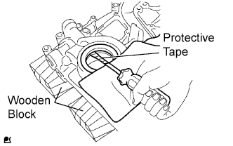
Place the timing chain cover on wooden blocks.
-
Using a screwdriver with its tip taped, pry out the oil seal.
-
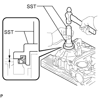
Using SST and a hammer, tap in a new oil seal until its surface is flush with the timing chain cover edge.
- SST
- 09223-75010
- 09950-70010 ( 09951-07150 )
Tech Tips
When installing the crankshaft pulley, check the shape of the pulley. The correct pulley has a groove Click here.
Note
-
Keep the lip free from foreign matter.
-
Do not tap the oil seal at an angle.
-
Apply a light coat of MP grease to a new oil seal lip.
-
-
REPLACE ENGINE REAR OIL SEAL
-
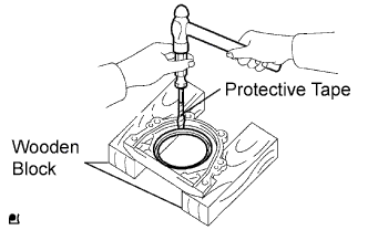
Place the oil seal retainer on wooden blocks.
-
Using a screwdriver with its tip taped and hammer, tap out the oil seal.
-
Place the oil seal retainer on wooden blocks.
-
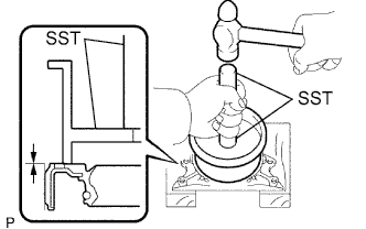
Using SST and hammer, tap in the oil seal until its surface is flush with the oil seal retainer edge.
- SST
- 09223-15030
- 09950-70010 ( 09951-07150 )
Note
-
Keep the lip free from foreign matter.
-
Do not tap the oil seal at an angle.
-
-
REPLACE INTAKE VALVE GUIDE BUSH
-

Heat the cylinder head to 80 to 100°C (176 to 212°F).
-
Place the cylinder head on wooden blocks.
-
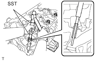
Using SST and a hammer, tap out the guide bush.
- SST
- 09201-01055
- 09950-70010 ( 09951-07100 )
-
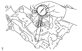
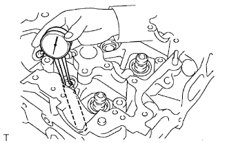
Using a caliper gauge, measure the bush bore diameter of the cylinder head.
Standard cylinder bore diameter 10.285 to 10.306 mm (0.4049 to 0.4057 in.) -
Select a new guide bush (STD or O/S 0.05).
Bush Bore Diameter Bush Size 10.285 to 10.306 mm (0.4049 to 0.4057 in.) Use STD 10.335 to 10.356 mm (0.4069 to 0.4077 in.) Use O/S 0.05 If the bush bore diameter of the cylinder head is greater than 10.306 mm (0.4057 in.), machine the bush bore to the dimension of 10.335 to 10.356 mm (0.4069 to 0.4077 in.) to install a O/S 0.05 valve guide bush.
If the bush bore diameter of the cylinder head is greater than 10.356 mm (0.4077 in.), replace the cylinder head.
-
Heat the cylinder head to 80 to 100°C (176 to 212°F).
-
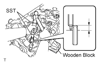
Place the cylinder head on wooden blocks.
-
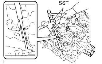
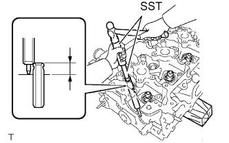
Using SST and a hammer, tap in a new valve guide bush to the specified protrusion height.
- SST
- 09201-01055
- 09950-70010 ( 09951-07100 )
Protrusion height 9.8 to 10.2 mm (0.3858 to 0.4016 in.) -
Using a sharp 5.5 mm reamer, ream the valve guide bush to obtain the standard specified clearance.
Standard oil clearance 0.025 to 0.060 mm (0.0010 to 0.0023 in.)
-
-
REPLACE EXHAUST VALVE GUIDE BUSH
-
Heat the cylinder head to 80 to 100°C (176 to 212°F).
-
Place the cylinder head on wooden blocks.
-
Using SST and a hammer, tap out the guide bush.
- SST
- 09201-01055
- 09950-70010 ( 09951-07100 )
-
Using a caliper gauge, measure the bush bore diameter of the cylinder head.
Standard cylinder bore diameter 10.285 to 10.306 mm (0.4049 to 0.4057 in.) -
Select a new guide bush (STD or O/S 0.05).
Bush Bore Diameter Bush Size 10.285 to 10.306 mm (0.4049 to 0.4057 in.) Use STD 10.335 to 10.356 mm (0.4069 to 0.4077 in.) Use O/S 0.05 If the bush bore diameter of the cylinder head is greater than 10.306 mm (0.4057 in.), machine the bush bore to the dimension of 10.335 to 10.356 mm (0.4069 to 0.4077 in.) to install a O/S 0.05 valve guide bush.
If the bush bore diameter of the cylinder head is greater than 10.356 mm (0.4077 in.), replace the cylinder head.
-
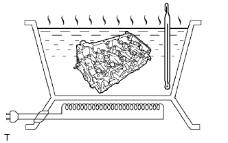
Heat the cylinder head to 80 to 100°C (176 to 212°F).
-
Place the cylinder head on the wooden blocks.
-
Using SST and a hammer, tap in a new valve guide bush to the specified protrusion height.
- SST
- 09201-01055
- 09950-70010 ( 09951-07100 )
Protrusion height 7.6 to 8.0 mm (0.2992 to 0.3150 in.) -
Using a sharp 5.5 mm reamer, ream the valve guide bush to obtain the standard specified clearance.
Standard oil clearance 0.030 to 0.065 mm (0.0012 to 0.0026 in.)
-
-
REPLACE CONNECTING ROD SMALL END BUSH
-
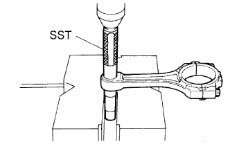
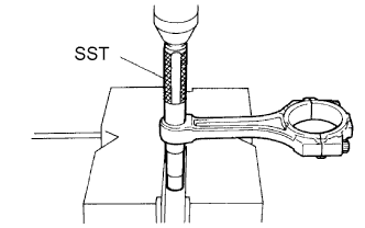
Using SST and a press, press out the bush.
- SST
- 09222-30010
-
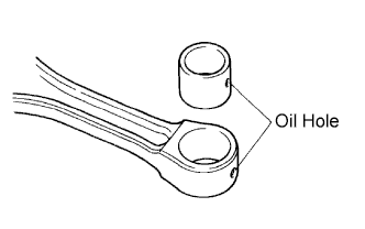
Align the oil holes of a new bush and the connecting rod.
-
Using SST and a press, press in the bush.
- SST
- 09222-30010
-
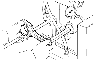
Using a pin hole grinder, hone the bush to obtain the standard specified clearance between the bush and piston pin.
-
Check that the piston pin fits at normal room temperature.
-
Coat the piston pin with engine oil, and push it into the connecting rod with your thumb.
-
-