EGR VALVE INSTALLATION
PROCEDURE
INSTALL ELECTRIC EGR CONTROL VALVE ASSEMBLY
-
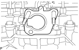
*1
Protrusion
Install a new gasket.
Note:Make sure the protrusion of the gasket is facing upward as shown in the illustration.
Install the electric EGR control valve assembly.
-
INSTALL NO. 2 EGR PIPE SUB-ASSEMBLY
Install a new gasket to the No. 2 EGR pipe sub-assembly.
Tip:Make sure that the claw of the gasket faces the No. 2 EGR pipe sub-assembly.
Install a new gasket to the electric EGR control valve assembly.
-
*1
Nut
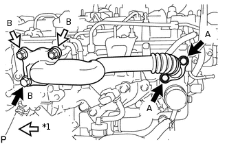
Temporarily install the No. 2 EGR pipe sub-assembly with the 3 bolts and 2 nuts.
Bolt Length
Item
Specified Condition
Bolt A
25 mm (0.984 in.)
Bolt B
70 mm (2.76 in.)
Tighten the 2 bolts labeled A shown in the illustration.
24 N*m
245 kgf*cm
18 ft.*lbf
Tighten the bolt and 2 nuts labeled B shown in the illustration.
24 N*m
245 kgf*cm
18 ft.*lbf
Connect the electric EGR control valve connector.
CONNECT NO. 8 WATER BY-PASS HOSE
Connect the No. 8 water by-pass hose to the electric EGR control valve assembly, and slide the clamp to secure the hose.
CONNECT NO. 7 WATER BY-PASS HOSE
Connect the No. 7 water by-pass hose to the electric EGR control valve assembly, and slide the clamp to secure the hose.
INSTALL EGR VALVE BRACKET
Install the EGR valve bracket with the 3 bolts.
24 N*m
245 kgf*cm
18 ft.*lbf
Connect the 2 connectors and attach the 2 wire harness clamps.
ADD ENGINE COOLANT
INSPECT FOR COOLANT LEAK
INSTALL NO. 1 ENGINE UNDER COVER
INSTALL NO. 1 ENGINE COVER
PERFORM ELECTRIC EGR CONTROL VALVE FULLY CLOSED POSITION LEARNING
Tip:Be sure to turn off the ignition switch before performing this operation.
Turn the ignition switch to ON.
Turn the ignition switch off and wait 30 seconds.
Tip:The fully closed position of the electric EGR control valve assembly is learned when the ignition switch is turned off.