SFI SYSTEM Starter Signal Circuit
| DTC Code | DTC Name |
|---|---|
| Starter Signal Circuit |
DESCRIPTION
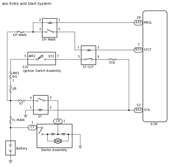
w/o Entry and Start System
While the engine is being cranked, current flows from terminal ST2 of the ignition switch assembly to the ST CUT relay and also flows to terminal STA of the ECM (STA Signal). The ECM uses the STA signal to control the fuel injection and ignition timing when the engine starts.
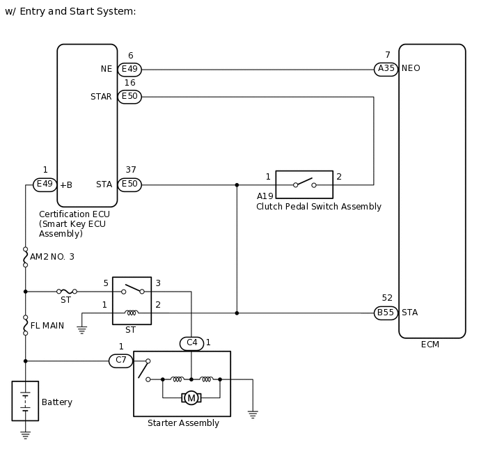
w/ Entry and Start System
While the engine is being cranked, current flows from terminal STAR of the certification ECU (smart key ECU) to clutch pedal switch assembly and also flows to terminal STA of the ECM (STA signal).
WIRING DIAGRAM
CAUTION / NOTICE / HINT
Inspect the fuses for circuits related to this system before performing the following procedure.
PROCEDURE
INSPECT ST RELAY
Inspect the ST relay.
Result
Proceed to
OK
NG
NG REPLACE ST RELAY
CHECK TERMINAL VOLTAGE (POWER SOURCE OF ST RELAY)
Remove the ST relay from the No. 1 engine room relay block.
Measure the voltage according to the value(s) in the table below.
Standard Voltage
Tester Connection
Condition
Specified Condition
5 (ST relay) - Body ground
Always
11 to 14 V
Result
Proceed to
OK
NG
NG REPAIR OR REPLACE HARNESS OR CONNECTOR (ST RELAY - BATTERY)
CHECK TERMINAL VOLTAGE (POWER SOURCE OF STARTER ASSEMBLY)
Disconnect the starter assembly connector.
Measure the voltage according to the value(s) in the table below.
Standard Voltage
Tester Connection
Condition
Specified Condition
C7-1 - Body ground
Always
11 to 14 V
Result
Proceed to
OK
NG
NG REPAIR OR REPLACE HARNESS OR CONNECTOR (STARTER ASSEMBLY - BATTERY)
CHECK HARNESS AND CONNECTOR (ST RELAY - STARTER ASSEMBLY)
Remove the ST relay from the No. 1 engine room relay block.
Disconnect the starter assembly connector.
Measure the resistance according to the value(s) in the table below.
Standard Resistance
Tester Connection
Condition
Specified Condition
3 (ST relay) - C4-1
Always
Below 1 Ω
3 (ST relay) or C4-1 - Body ground and other terminals
Always
10 kΩ or higher
Result
Proceed to
OK
NG
NG REPAIR OR REPLACE HARNESS OR CONNECTOR
CHECK HARNESS AND CONNECTOR (ST RELAY - BODY GROUND)
Remove the ST relay from the No. 1 engine room relay block.
Measure the resistance according to the value(s) in the table below.
Standard Resistance
Tester Connection
Condition
Specified Condition
1 (ST relay) - Body ground
Always
Below 1 Ω
Result
Result
Proceed to
OK (w/ Entry and Start System)
A
OK (w/o Entry and Start System)
B
NG
C
B CHECK HARNESS AND CONNECTOR (ST CUT RELAY - ST RELAY - ECM)Click here
C REPAIR OR REPLACE HARNESS OR CONNECTOR
CHECK HARNESS AND CONNECTOR (CERTIFICATION ECU (SMART KEY ECU ASSEMBLY) - ST RELAY - CLUTCH PEDAL SWITCH ASSEMBLY - ECM)
Disconnect the certification ECU (smart key ECU assembly) connector.
Remove the ST relay from the No. 1 engine room relay block.
Disconnect the clutch pedal switch assembly connector.
Disconnect the ECM connector.
Measure the resistance according to the value(s) in the table below.
Standard Resistance
Tester Connection
Condition
Specified Condition
E50-37 (STA) - B55-52 (STA)
Always
Below 1 Ω
2 (ST relay) - B55-52 (STA)
Always
Below 1 Ω
A19-1 - B55-52 (STA)
Always
Below 1 Ω
E50-37 (STA), 2 (ST relay), A19-1 or B55-52 (STA) - Body ground and other terminals
Always
10 kΩ or higher
Result
Proceed to
OK
NG
NG REPAIR OR REPLACE HARNESS OR CONNECTOR
INSPECT CLUTCH PEDAL SWITCH ASSEMBLY
Inspect the clutch pedal switch assembly.
Result
Proceed to
OK
NG
CHECK HARNESS AND CONNECTOR (CERTIFICATION ECU (SMART KEY ECU) - CLUTCH PEDAL SWITCH ASSEMBLY)
Disconnect the certification ECU (smart key ECU) connector.
Disconnect the clutch pedal switch assembly connector.
Measure the resistance according to the value(s) in the table below.
Standard Resistance
Tester Connection
Condition
Specified Condition
E50-16 (STAR) - A19-2
Always
Below 1 Ω
E50-16 (STAR) or A19-2 - Body ground and other terminals
Always
10 kΩ or higher
Result
Proceed to
OK
NG
NG REPAIR OR REPLACE HARNESS OR CONNECTOR
CHECK HARNESS AND CONNECTOR (ST CUT RELAY - ST RELAY - ECM)
Remove the ST CUT relay from the center relay block.
Remove the ST relay from the No. 1 engine room relay block.
Disconnect the ECM connector.
Measure the resistance according to the value(s) in the table below.
Standard Resistance
Tester Connection
Condition
Specified Condition
4 (ST CUT relay) - B55-52 (STA)
Always
Below 1 Ω
2 (ST relay) - B55-52 (STA)
Always
Below 1 Ω
4 (ST CUT relay), 2 (ST relay) or B55-52 (STA) - Body ground and other terminals
Always
10 kΩ or higher
Result
Proceed to
OK
NG
NG REPAIR OR REPLACE HARNESS OR CONNECTOR
INSPECT IGNITION SWITCH ASSEMBLY
Inspect the ignition switch assembly.
Result
Proceed to
OK
NG
INSPECT ST CUT RELAY
Inspect the ST CUT relay.
Result
Proceed to
OK
NG
NG REPLACE ST CUT RELAY
CHECK HARNESS AND CONNECTOR (IGNITION SWITCH ASSEMBLY - ST CUT RELAY)
Disconnect the ignition switch assembly connector.
Remove the ST CUT relay from the center relay block.
Measure the resistance according to the value(s) in the table below.
Standard Resistance
Tester Connection
Condition
Specified Condition
E21-7 (ST2) - 3 (ST CUT relay)
Always
Below 1 Ω
E21-7 (ST2) or 3 (ST CUT relay) - Body ground and other terminals
Always
10 kΩ or higher
Result
Proceed to
OK
NG
NG REPAIR OR REPLACE HARNESS OR CONNECTOR
CHECK TERMINAL VOLTAGE (POWER SOURCE OF ST CUT RELAY)
Remove the ST CUT relay from the center relay block.
Turn the ignition switch to ON.
Measure the voltage according to the value(s) in the table below.
Standard Voltage
Tester Connection
Condition
Specified Condition
1 (ST CUT relay) - Body ground
Ignition switch ON
11 to 14 V
Result
Proceed to
OK
NG
NG CHECK HARNESS AND CONNECTOR (EFI MAIN RELAY - ST CUT RELAY)Click here
CHECK HARNESS AND CONNECTOR (ST CUT RELAY - ECM)
Remove the ST CUT relay from the center relay block.
Disconnect the ECM connector.
Measure the resistance according to the value(s) in the table below.
Standard Resistance
Tester Connection
Condition
Specified Condition
2 (ST CUT relay) - B55-7 (STCT)
Always
Below 1 Ω
2 (ST CUT relay) or B55-7 (STCT) - Body ground and other terminals
Always
10 kΩ or higher
Result
Proceed to
OK
NG
OK REPAIR OR REPLACE HARNESS OR CONNECTOR (BATTERY - IGNITION SWITCH ASSEMBLY)
NG REPAIR OR REPLACE HARNESS OR CONNECTOR
CHECK HARNESS AND CONNECTOR (EFI MAIN RELAY - ST CUT RELAY)
Remove the EFI MAIN relay from the No. 1 engine room relay block.
Remove the ST CUT relay from the center relay block.
Measure the resistance according to the value(s) in the table below.
Standard Resistance
Tester Connection
Condition
Specified Condition
5 (EFI MAIN relay) - 1 (ST CUT relay)
Always
Below 1 Ω
5 (EFI MAIN relay) or 1 (ST CUT relay) - Body ground and other terminals
Always
10 kΩ or higher
Result
Proceed to
OK
NG
NG REPAIR OR REPLACE HARNESS OR CONNECTOR