AUTOMATIC TRANSMISSION SYSTEM
-
FUNCTION OF MAIN COMPONENTS
Component Function Torque Converter Assembly
-
Transmits the engine power to the transmission.
-
Increases engine torque.
Oil Pump Provides oil pressure necessary for transmission operation. No. 1 Clutch (C1) Connects the input shaft and the intermediate shaft. No. 2 Clutch (C2) Connects the input shaft and the center planetary gear assembly. No. 1 Brake (B1) Locks the rotations of the front planetary carrier and the center planetary ring gear. No. 2 Brake (B2) Locks the rotation of the rear planetary ring gear. No. 3 Brake (B3) Locks the rotation of the front planetary ring gear. 1-way Clutch (F) Locks the counterclockwise rotations of the center planetary carrier and the rear planetary ring gear. Planetary Gears Change the power transmission route in accordance with clutch and brake operation, and increase or decrease output shaft revolution accordingly. Solenoid Valve (SL1) Performs shift controls. Solenoid Valve (SL2) Performs shift controls. Solenoid Valve (SL3) Performs shift controls. Solenoid Valve (SL4) Performs shift controls. Solenoid Valve (SLT) Controls line pressure. Solenoid Valve (SLU)
-
Performs lock-up clutch controls.
-
Performs B2 brake hydraulic pressure controls (only for the 1st range when the S mode is selected).
Solenoid Valve (SL) Shifts between lock-up hydraulic pressure and B2 brake hydraulic pressure. No. 1 ATF Temperature Sensor Detects the ATF temperature. No. 2 ATF Temperature Sensor Detects the ATF temperature. Transmission Revolution Sensor (NT) Detects the input speed of the transmission. Transmission Revolution Sensor (SP2) Detects the output speed of the transmission. Park/Neutral Position Switch Assembly Detects the shift lever position (P, R, N, D). Transmission Floor Shift Assembly Transmission Control Switch
-
Detects that the shift lever is in S.
-
Detects the driver's upshift and downshift operations when the shift lever is in S.
Combination Switch Assembly ECO Mode Switch Selects the drive mode (ECO mode). PWR Mode Switch Selects the drive mode (PWR mode). Combination Meter Assembly*1 Shift Position and Shift Range Indicator
-
Indicates the shift lever position.
-
Indicates the shift range.
ECO Mode Indicator Illuminates when the ECO mode switch is pressed and informs the driver that ECO mode is active. PWR Mode Indicator Illuminates when the PWR mode switch is pressed and informs the driver that PWR mode is active. ATF Temperature Warning Light Illuminates when the ATF is at a high temperature. MIL Illuminates or blinks to inform the driver when the ECM detects a malfunction. Multi Buzzer Sounds when downshift operation is rejected in S mode. Combination Meter Assembly*2 Shift Position and Shift Range Indicator
-
Indicates the shift lever position.
-
Indicates the shift range.
ECO Mode Indicator Illuminates when the ECO mode switch is pressed and informs the driver that ECO mode is active. PWR Mode Indicator Illuminates when the PWR mode switch is pressed and informs the driver that PWR mode is active. Multi-information Display Displays a message when the ATF is at a high temperature. MIL Illuminates or blinks to inform the driver when the ECM detects a malfunction. Multi Buzzer Sounds when downshift operation is rejected in S mode. Combination Meter Assembly*3 Multi-information Display
-
Displays the shift lever position.
-
Displays the shift range.
-
Displays the drive mode (ECO or PWR).
-
Displays a message when the ATF is at a high temperature.
MIL Illuminates or blinks to inform the driver when the ECM detects a malfunction. Multi Buzzer Sounds when downshift operation is rejected in S mode. ECM
-
Controls each solenoid valve and engine output in response to signals from each sensor and switch.
-
When the ECM detects a malfunction, it makes a diagnosis and memorizes the failed section.
Air Conditioning Amplifier Assembly*4 Sends a shift-up tardiness control signal to the ECM. *1: Models with analog type combination meter assembly
*2: Models with analog type combination meter assembly with dot display type multi-information display
*3: Models with Optitron type combination meter assembly
*4: Models with automatic air conditioning system
-
-
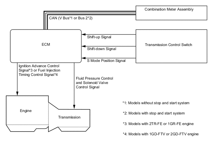
SYSTEM CONTROL
Electronic Control of Automatic Transmission Control Outline Powertrain Cooperative Control Controls both the shift control and engine output control in an integrated way, thus achieving excellent shift characteristics and driveability. Shift Timing Control The ECM sends current to solenoid valves (SL1), (SL2), (SL3), (SL4) and/or (SL) based on signals from various sensors in order to shift the gears. Line Pressure Control Actuates the solenoid valve (SLT) to control the line pressure in accordance with information from the ECM and the operating conditions of the transmission. Clutch Pressure Optimal Control The solenoid valves (SL1), (SL2), (SL3), (SL4), (SLT) and (SLU) minutely control the clutch pressure in accordance with the engine output and driving conditions of the transmission. Clutch to Clutch Pressure Control By utilizing pressure output from solenoid valves (SL1), (SL2), (SL3) and (SL4) based on drive signals sent from the ECM, each of the clutch and brake hydraulic pressures can be controlled directly and independently. Vehicle Lift Control The clutch release speed has been optimized to restrain the upward movement of the vehicle when the shift lever is moved from D to N. Shift Down Control The hydraulic passages and control have been optimized in order to ensure a smooth shift feel during downshifting to accelerate the vehicle. Engine Torque Control Retards the engine ignition timing*1 or fuel injection volume*2 temporarily to improve shift feeling while upshifts or downshifts occur. Lock-up Timing Control The ECM sends current to the solenoid valve (SLU) based on signals from various sensors and engages or disengages the lock-up clutch. Flex Lock-up Clutch Control Controls the solenoid valve (SLU), provides an intermediate mode for when the lock-up clutch is between on and off, and increases the operating range of the lock-up clutch to improve fuel economy. Coast Downshift Control The ECM performs downshifts before fuel cut ends to prevent the engine speed from decreasing and maintain the fuel cut. Artificial Intelligence Shift Control (AI-shift Control) Based on the signals from various sensors, the ECM determines the road conditions and the intention of the driver. Thus, an appropriate shift pattern is automatically determined, which improves driveability. Multi-mode Automatic Transmission The ECM appropriately controls the automatic transmission in accordance with the shift range position selected while the shift lever is in S. ATF High Temperature Control When the ATF is at a high temperature, normal shifting characteristics will be changed to shifting characteristics which actively utilize the low gear range to prevent the oil temperature from rising further. *1: Models with 2TR-FE or 1GR-FE engine
*2: Models with 1GD-FTV or 2GD-FTV engine
-
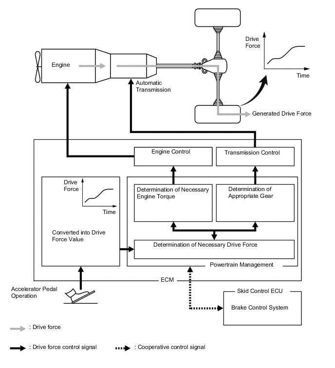
Powertrain Cooperative Control
-
The Driving Response and Acceleration Management System (DRAMS) is used for this model. This system integrally controls the engine, transmission and other driving related controls in order to improve vehicle maneuverability and driving comfort, as well as provide optimal drive feeling as a whole, including the behavior of the vehicle, while taking into account the drivers' needs and environment.
-
By integrally controlling the engine and automatic transmission using this system, acceleration maneuvers are replaced with drive force demanded by the driver. As a result, quick response and a high quality driving experience in accordance with the driver's intentions is achieved, such as when accelerating or decelerating, starting or stopping, or during gear shifts to provide demanded drive force while still producing a smoother shift transition.
-
Start Control (Models with 2TR-FE or 1GR-FE Engine)
-
With DRAMS, engine torque will optimally be controlled in a real-time manner in accordance with speed ratios between engine speed and turbine speed so that finely controlled starting capability has been provided while balancing the "reduction of a feel of jump and suppression of tire slipping" and "smooth responsiveness" when starting.
-
-
Integrated Drive Force Control (Models with 2TR-FE Engine)
-
By increasing drive force before making a downshift when accelerating, a feel of slowness after downshifting has been reduced, making it possible to balance smooth shift characteristic and responsiveness when accelerating.
-
-
-
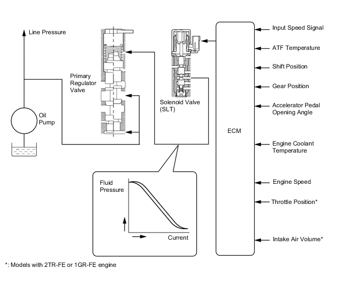
Line Pressure Control
-
In order to obtain predetermined line pressure characteristics in accordance with each sensor signal, the ECM activates the solenoid valve (SLT) to regulate the throttle pressure.
-
This makes it possible for the primary regulator valve to precisely and minutely control the line pressure in accordance with the engine output, thus providing smoother shift characteristics.
-
-
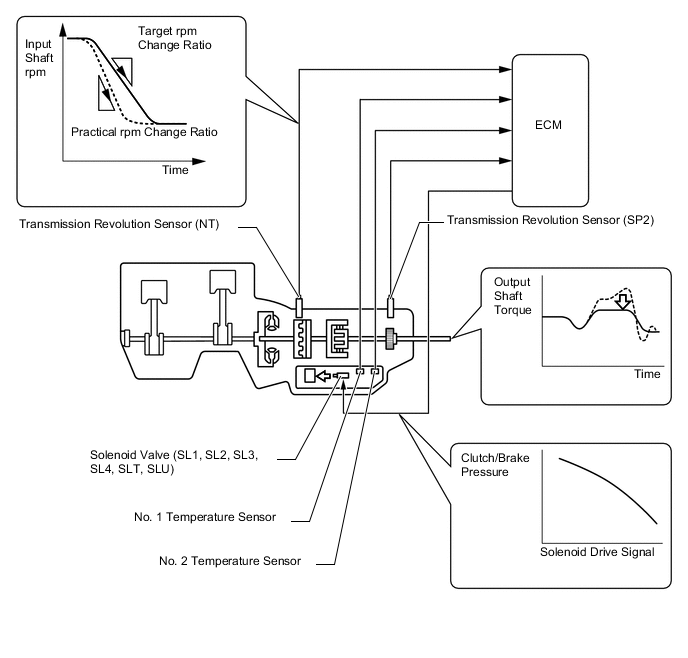
Clutch Pressure Optimal Control
-
The ECM monitors the signals from various types of sensors, such as the transmission revolution sensor (NT), allowing solenoid valves (SL1), (SL2), (SL3), (SL4), (SLT) and (SLU) to minutely control the clutch pressure in accordance with engine output and driving conditions. As a result, smooth shift characteristics are achieved.
-
-
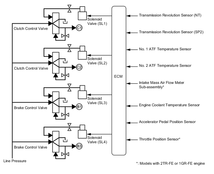
Clutch to Clutch Pressure Control
-
By using a clutch to clutch pressure control without using 1-way clutches in the 2nd or higher gears, a light, compact 6-speed automatic transmission has been provided.
-
By utilizing pressure output from solenoid valves (SL1), (SL2), (SL3) and (SL4) based on drive signals sent from the ECM, each of the clutch and brake hydraulic pressures can be controlled directly and independently.
-
-
Lock-up Timing Control
-
The ECM operates the lock-up timing control in order to improve fuel economy.
Lock-up Timing Control Operation Gear Position Shift Lever Position or Shift Range D, S6 S5 S4 1st X X X 2nd X X X 3rd X X X 4th ○ ○ ○ 5th ○ ○ - 6th ○ - - Tech Tips
○: Available
X: Does not operate
-: Not applicable
-
-
Flex Lock-up Clutch Control
-
During acceleration, partial control of the power transmission between the lock-up clutch and torque converter greatly boosts transmission efficiency in accordance with the driving conditions, improving fuel economy.
-
Even when the vehicle is decelerating (the accelerator pedal is released), flex lock-up clutch control operates. As a result, the fuel cut area is expanded and fuel economy is improved.
-
By allowing flex lock-up clutch control to continue operating during gearshifts, smooth torque transmission is obtained. As a result, fuel economy and driveability are improved.
-
For flex lock-up clutch control, H infinity (H∞) control theory is used to achieve a high level of system stability and response to various characteristic changes.
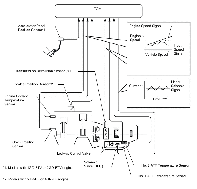
Figure 1. Flex Lock-up Operating Range
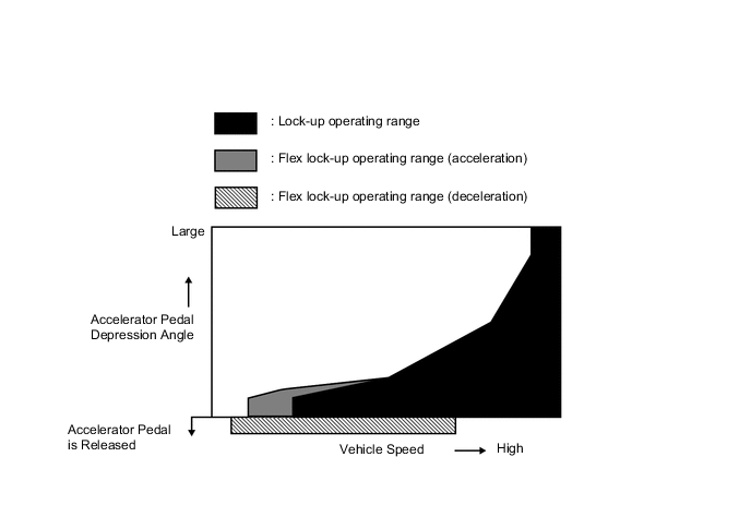
Flex Lock-up Clutch Control Operation (Acceleration) Gear Shift Lever Position or Shift Range D, S6 S5 S4 1st X X X 2nd X X X 3rd X X X 4th ○ ○ ○ 5th ○ ○ - 6th ○ - - Tech Tips
○: Operates
X: Does not operate
-: Not applicable
Flex Lock-up Clutch Control Operation (Deceleration) Gear Shift Lever Position or Shift Range D, S6 S5 S4 1st X X X 2nd X X X 3rd X X X 4th ○ ○ X 5th ○ ○ - 6th ○ - - Tech Tips
○: Operates
X: Does not operate
-: Not applicable
-
-
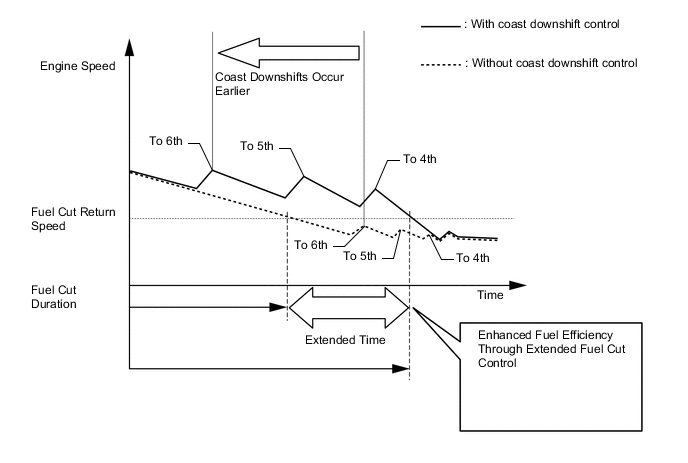
Coast Downshift Control
-
Downshift control is used when decelerating, allowing for low fuel consumption by extending fuel cut control as much as possible.
-
By performing flex lock-up control and downshift control at the same time when decelerating, a decrease of engine speed has been suppressed, while extending fuel cut control as much as possible without lowering the engine speed below the fuel cut recovery speed.
-
By expanding operating gears and widening operating areas through close-gear ratios, fuel efficiency has significantly been enhanced and drivability has been improved by optimizing deceleration force when controls are activated.
-
-
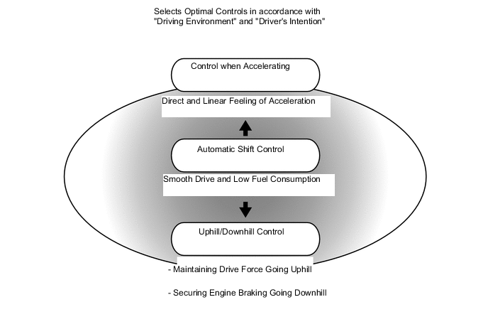
Artificial Intelligence-shift Control (AI-shift Control)
-
AI-shift control selects optimal controls in accordance with "driving environment" and the "driver's intention" based on the degree of accelerator opening, vehicle speed, brake signals, etc.
-
Smooth driving and low fuel consumption have been achieved while driving normally. A strong and linear feeling of acceleration has been provided when accelerating. A direct feeling of deceleration through engine braking and high fuel efficiency have been achieved when decelerating.
-
Under road condition support control, the ECM identifies the throttle valve opening angle, accelerator pedal opening angle and vehicle speed to determine whether the vehicle is being driven uphill or downhill. Unnecessary upshifting is restrained to automatically achieve optimal drive force at all times while driving uphill. Downshifting is automatically conducted to achieve optimal engine brake force while driving downhill.
-
On models with 1GR-FE, 1GD-FTV or 2GD-FTV engine, when the accelerator pedal is quickly released, the shift range is held to improve engine brake force and responsiveness when accelerating again. Also, when the accelerator pedal is quickly depressed, a rapid downshift is performed to improve acceleration responsiveness.
Figure 2. Accelerator Pedal Quickly Released (Models with 1G-FE, 1GD-FTV or 2GD-FTV Engine)
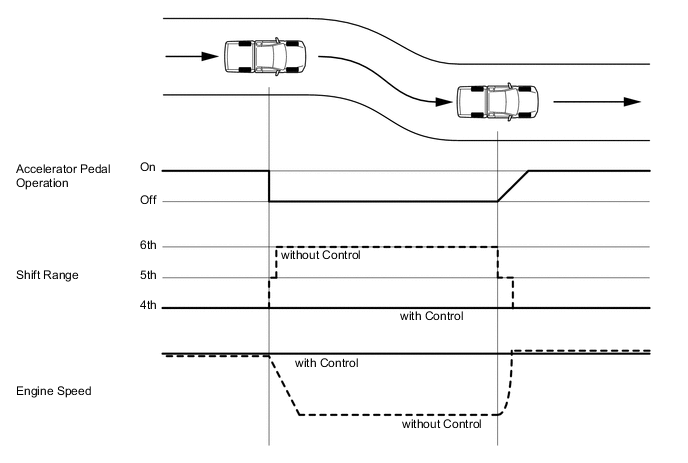
Figure 3. Accelerator Pedal Quickly Depressed

-
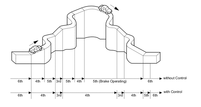
Higher gear settings have been added for high speed gears (5th and 6th gears). In order to balance the reduction of additional drive force and the improvement of fuel efficiency when driving at high speeds, a high speed gear effective utilization control is used.
-
By calculating the maximum additional drive force to be generated at high speed gears in a real-time manner, as well as determining the availability of high speed gears according to driving conditions (running resistance, driver's acceleration maneuvers), "balanced, improved fuel efficiency and driving capability" have been achieved.
Figure 4. Conditions Determining that Running in 6th Gear is Impossible (Examples)
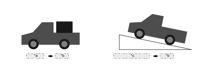
*a Heavy Load *b 5th Gear *c Accelerating on Slope Figure 5. Conditions Determining that Running in 6th Gear is Possible
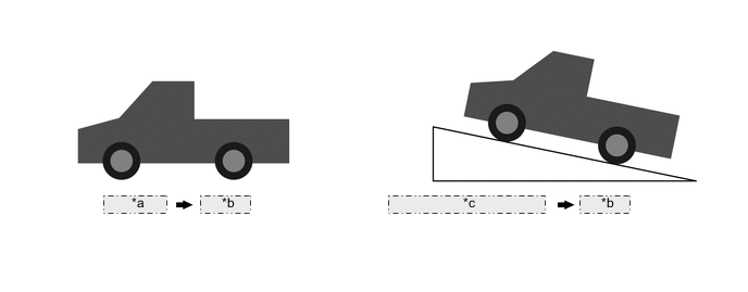
*a Light Load *b 6th Gear *c Constant Driving on Slope
-
-
Multi-mode Automatic Transmission
-
The driver can select the desired gear step by moving the shift lever "+" (forward) or to "-" (backward) while the shift lever is in S (6-speed sequential shiftmatic mode). Thus, the driver is able to change gear steps with a manual-like feel.
-
6-speed sequential shiftmatic mode can be selected from normal driving mode by moving the shift lever to S. The driver can change the gear step by selecting it using the shift lever.
-
The driver selects S mode by moving the shift lever to S. At this time, the S4 or S5 range is selected in accordance with the vehicle speed.
-
The ECM will restrict the changing of the shift range if it detects a malfunction in the automatic transmission system.
-
If the vehicle speed and engine speed exceed or go below a preset level in response to the driver's downshift operation request, changing the shift range will be prohibited. In this case, the buzzer in the combination meter will sound to alert the driver.
-
The shift lever position and the shift range are indicated by the shift position and shift range indicator*1 or multi-information display*2 in the combination meter assembly.
-
*1: Models with analog type combination meter assembly
-
*2: Models with Optitron type combination meter assembly
Figure 6. Models with Analog Type Combination Meter Assembly
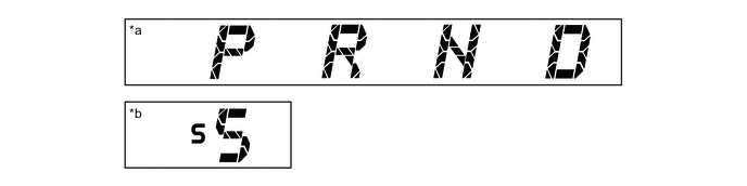
*a When Shift Lever is in P, R, N or D *b When Shift Lever is in S Figure 7. Models with Optitron Type Combination Meter Assembly
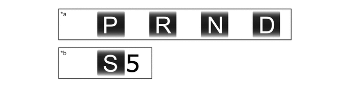
*a When Shift Lever is in P, R, N or D *b When Shift Lever is in S -
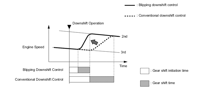
-
Blipping downshift control is used to improve shift change response and shift feeling in 6-speed sequential shiftmatic mode.
-
The blipping downshift control regulates each clutch and brake using the clutch to clutch pressure control, allowing them to be engaged smoothly and disengaged quickly. In addition, engine speed is boosted by the powertrain cooperative control, thus ensuring engine brake force. In this way, a smooth and quick downshift is achieved. In addition, quicker downshifting has been made available by directly controlling clutch pressure.
Tech Tips
If ATF and engine coolant temperatures are low, the shift change response will be the same as when blipping downshift control is not available.
-
-
-
FUNCTION
-
Drive Mode Select
-
The drive mode can be selected by operating the combination switch assembly (ECO mode switch or PWR mode switch).
Characteristics of Drive Mode Drive Mode Characteristics ECO Mode The ECM optimizes fuel economy and driving performance by gradually generating drive force in comparison to the accelerator pedal operation. At the same time, the ECM supports eco driving by optimizing air conditioning performance. PWR Mode The ECM improves acceleration performance and responsiveness by controlling the engine output and by changing the shift point of the transmission, thus achieving a sporty drive.
-
-
-
FAIL-SAFE
-
The fail-safe function minimizes the loss of operability when an abnormality occurs in a sensor or a solenoid valve.
-
For details, refer to the Repair Manual.
-
-
DIAGNOSIS
-
When the ECM detects a malfunction, it makes a diagnosis and memorizes the failed section. Furthermore, the ECM illuminates or blinks the MIL in the combination meter assembly to inform the driver.
-
The ECM will also store the Diagnostic Trouble Codes (DTCs) of the malfunctions. The DTCs can be read by connecting a Global TechStream (GTS) to the DLC3.
-
For details, refer to the Repair Manual.
-