FRONT DOOR REASSEMBLY

CAUTION / NOTICE / HINT
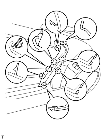
Tech Tips
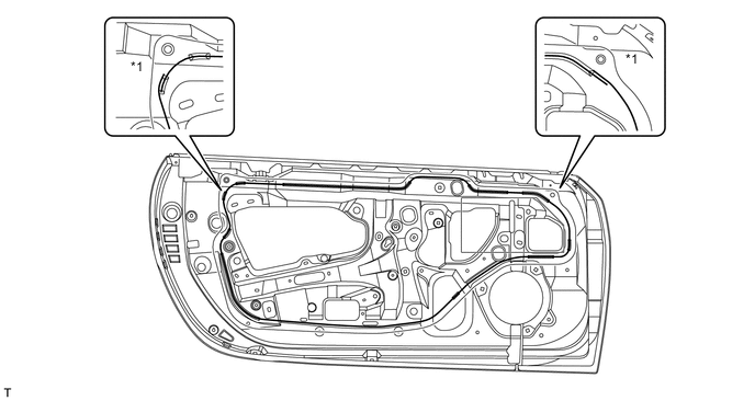
Use the same procedure for both the RH and LH sides.
PROCEDURE
-
INSTALL FRONT DOOR HOLE COVER
-
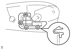
Insert the front door hole cover with the 4 claws.
-
-
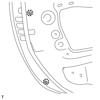
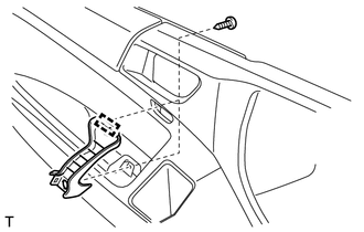
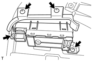
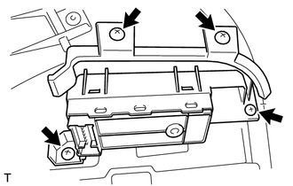
INSTALL DOOR SIDE AIR BAG SENSOR
-
INSTALL FRONT DOOR GLASS OUTER WEATHERSTRIP ASSEMBLY
-
INSTALL FRONT DOOR PANEL CUSHION
-
Engage the 2 claws and install 2 new front door panel cushions.
-
-
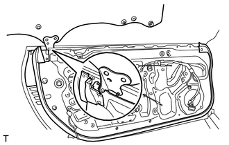
INSTALL FRONT DOOR CHECK ASSEMBLY
-
Apply MP grease to the sliding areas of the front door check assembly.
-
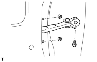
Apply adhesive to the threads of the bolt.
Adhesive Toyota Genuine Adhesive 1324, Three Bond 1324 or equivalent -
Install the bolt.
- Torque:
- 33 N*m { 337 kgf*cm, 24 ft.*lbf }
-
Install the front door check assembly with the 2 nuts.
- Torque:
- 7.5 N*m { 76 kgf*cm, 66 in.*lbf }
-
-
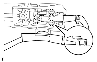
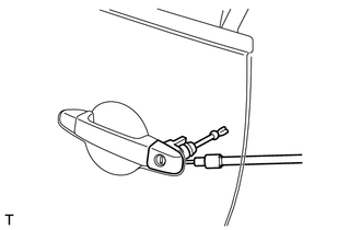
INSTALL FRONT DOOR LOCK OPEN ROD
-
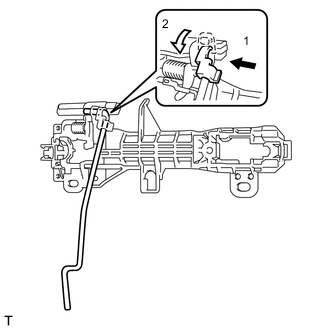
Install the front door lock open rod as indicated by the arrows, in the order shown in the illustration.
-
-
INSTALL FRONT DOOR OUTSIDE HANDLE FRAME SUB-ASSEMBLY
-
Apply MP grease to the sliding parts on the front door outside handle frame sub-assembly.
-
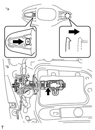
Text in Illustration *a Outside Vehicle *b Inside Vehicle Engage the claw.
-
Using a T30 "TORX" socket wrench, install the front door outside handle frame sub-assembly with the screw.
- Torque:
- 7.5 N*m { 76 kgf*cm, 66 in.*lbf }
-
-
INSTALL FRONT DOOR FRONT OUTSIDE HANDLE PAD
-
Engage the 3 claws and install the front door front outside handle pad.
-
-
INSTALL FRONT DOOR REAR OUTSIDE HANDLE PAD
-
Engage the 2 claws and install the front door rear outside handle pad.
-
-
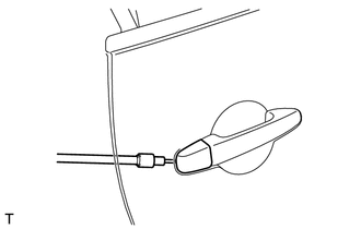
INSTALL FRONT DOOR OUTSIDE HANDLE ASSEMBLY (w/ Entry and Start System)
-
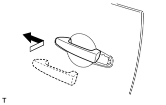
Insert the front end of the front door outside handle assembly into the front door outside handle frame sub-assembly.
-
Insert the rear end of the front door outside handle assembly into the front door outside handle frame sub-assembly, and then slide the front door outside handle assembly toward the front of the vehicle to install it.
-
Connect the connector.
-
Engage the 3 claws.
-
Engage the clamp.
-
-
INSTALL FRONT DOOR OUTSIDE HANDLE ASSEMBLY (w/o Entry and Start System)
-
Insert the front end of the front door outside handle assembly into the front door outside handle frame sub-assembly.
-
Insert the rear end of the front door outside handle assembly into the front door outside handle frame sub-assembly, and then slide the front door outside handle assembly toward the front of the vehicle to install it.
-
-
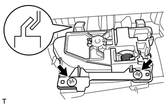
INSTALL FRONT DOOR LOCK ASSEMBLY
-
INSTALL FRONT DOOR OUTSIDE HANDLE COVER (for Driver Side)
-
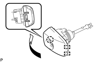
Engage the claw and 2 guides, and install the front door outside handle cover to the front door lock cylinder assembly.
-
-
INSTALL FRONT DOOR LOCK CYLINDER ASSEMBLY (for Driver Side)
-
Install the front door outside handle cover with front door lock cylinder assembly.
Tech Tips
Make sure that the front door lock cylinder rod is inserted into the front door lock assembly.
-
Using a T30 "TORX" socket wrench, install the front door lock cylinder assembly with the screw.
- Torque:
- 7.5 N*m { 76 kgf*cm, 66 in.*lbf }
-
-
INSTALL FRONT DOOR OUTSIDE HANDLE COVER (for Front Passenger Side)
-
Using a T30 "TORX" socket wrench, install the front door outside handle cover with the screw.
- Torque:
- 7.5 N*m { 76 kgf*cm, 66 in.*lbf }
-
-
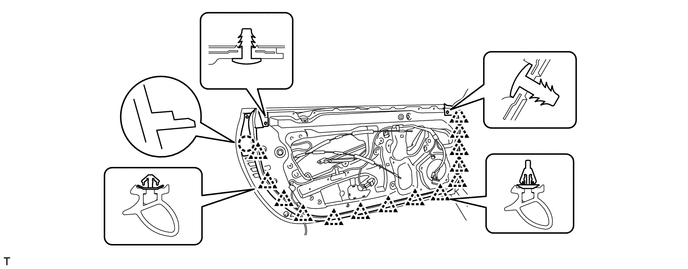
INSTALL FRONT DOOR WEATHERSTRIP
-
Engage the 16 clips.
-
Engage the claw.
-
Install the front door weatherstrip with the screw.
-
-
INSTALL POWER WINDOW REGULATOR MOTOR ASSEMBLY
-
INSTALL FRONT DOOR WINDOW REGULATOR SUB-ASSEMBLY
-
Apply MP grease to the sliding parts of the front door window regulator sub-assembly.
-
Install the temporary bolt to the front door window regulator sub-assembly.
-
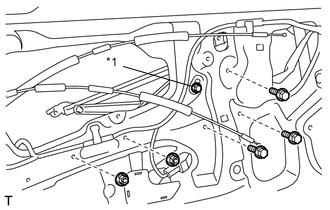
Text in Illustration *1 Temporary Bolt Temporarily install the front door window regulator sub-assembly.
-
Tighten the 3 bolts and 2 nuts.
- Torque:
- 7.5 N*m { 76 kgf*cm, 66 in.*lbf }
-
Tighten the temporary bolt.
- Torque:
- 7.5 N*m { 76 kgf*cm, 66 in.*lbf }
-
Connect the connector.
-
-
INSTALL FRONT DOOR SASH STOPPER
-
Install the front door sush stopper with the bolt.
- Torque:
- 7.5 N*m { 76 kgf*cm, 66 in.*lbf }
-
-
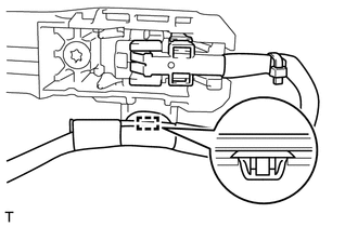
INSTALL FRONT DOOR SUSH
-
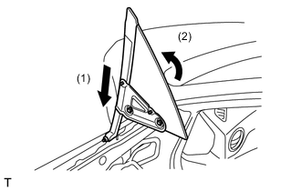
Insert the front door sush so that it is perpendicular to the front door frame, in the order shown in the illustration.
-
Rotate the front door sush 90°.
Note
Do not damage the front door sush.
-
Install the front door sush with the 3 nuts.
- Torque:
- Nut(A)
- 14 N*m { 143 kgf*cm, 10 ft.*lbf }
- Torque:
- Nut(B)
- 7.5 N*m { 76 kgf*cm, 66 in.*lbf }
-
-
INSTALL FRONT DOOR GLASS SUB-ASSEMBLY
-
Connect the cable to the negative (-) battery terminal.
-
Connect the power window regulator master switch assembly connector (for driver side).
-
Connect the power window regulator switch assembly connector (for front passenger side).
-
Move the front door glass sub-assembly until the 2 nuts can be seen through the service holes.
-
Disconnect the cable from the negative (-) battery terminal.
-
Disconnect the power window regulator master switch assembly connector (for driver side).
-
Disconnect the power window regulator switch assembly connector (for front passenger side).
-
Insert the front door glass sub-assembly into the front door frame from the position indicated in the illustration.
Note
Do not damage the front door weatherstrip.
Tech Tips
The front door glass sub-assembly can only be installed from the position indicated in the illustration, so install it while sliding the front door rear lower frame sub-assembly.
-
Insert the grommet of front door glass assembly into the rail of the front door rear lower frame sub-assembly.
-
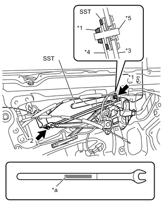
Text in Illustration *1 Nut A *2 Nut B *3 Front Door Glass Sub-assembly *4 Front Door Window Regulator Sub-assembly *5 Bolt *a SST Number Install a new nut B temporarily to the front door glass sub-assembly.
-
Install SST as shown in the illustration.
- SST
- 09801-18010
Tech Tips
The SST number on SST must be visible.
-
Secure the bolt using SST, and then tighten a new nut A to the specified torque.
- Torque:
- 7.5 N*m { 76 kgf*cm, 66 in.*lbf }
-
Tighten nut B to the specified torque.
- Torque:
- 7.5 N*m { 76 kgf*cm, 66 in.*lbf }
-
-
INSTALL DOOR GLASS INNER STABILIZER
-
Install the door glass inner stabilizer with the bolt.
- Torque:
- 7.5 N*m { 76 kgf*cm, 66 in.*lbf }
-
-
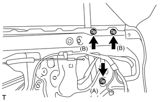
INSTALL FRONT DOOR REAR LOWER FRAME SUB-ASSEMBLY
-
Install the front door rear lower frame sub-assembly with the 3 nuts.
- Torque:
- 14 N*m { 143 kgf*cm, 10 ft.*lbf }
-
-
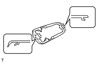
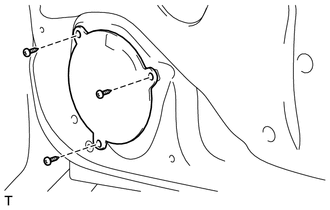
INSTALL OUTER REAR VIEW MIRROR SUB-ASSEMBLY
-
ADJUST FRONT DOOR GLASS SUB-ASSEMBLY
-
Check the front door glass sub-assembly Click here.
-
Adjust the front door glass sub-assembly Click here.
-
-
INSTALL FRONT DOOR SERVICE HOLE COVER
-
Apply butyl tape to the front door panel.
-
Pass the front door lock remote control cable assembly and the front door inside locking cable assembly through a new front door service hole cover.
Text in Illustration *1 Reference Point - - -
Attach the front door service hole cover according to the reference points on the front door panel.
Note
-
Overlay the butyl tape in lengths of 20 cm (7.874 in.) or more.
-
Do not block the drip holes in the front door panel with butyl tape.
-
Securely install the front door service hole cover preventing wrinkles and air bubbles.
-
-
Connect each connector.
-
-
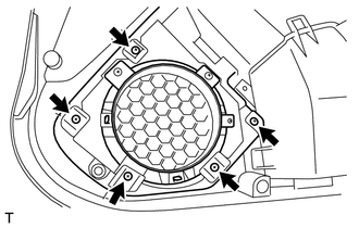
INSTALL FRONT NO. 1 SPEAKER ASSEMBLY (w/ Front Speaker)
-
INSTALL FRONT DOOR SPEAKER HOLE COVER (w/o Front Speaker)
-
Install the front door speaker hole cover with the 3 screws.
-
-
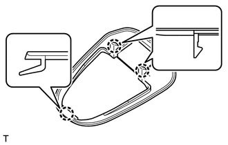
INSTALL FRONT DOOR GLASS INNER WEATHERSTRIP
-
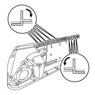
Engage the 9 claws to install a new front door glass inner weatherstrip to the front door trim board sub-assembly as shown in the illustration.
-
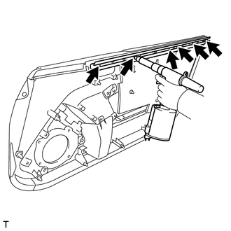
Install a nose piece to an air riveter, and then insert the mandrel part of a new rivet into the nose piece.
-
Hold the riveter perpendicular against the moulding and install the 6 rivets.
Tech Tips
If the rivet cannot be cut, pull it once again to cut it. Also, be sure to cut off the head.
Note
-
Do not pry the rivet with the riveter as this will cause damage to the riveter and mandrel.
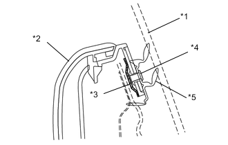
Text in Illustration *1 Riveter *2 Mandrel *a Incorrect *b Correct -
Confirm that the rivets are seated properly against the front door glass inner weatherstrip.
Text in Illustration *1 Riveter *a Incorrect *b Correct -
Do not tilt the riveter when installing the rivet to the front door glass inner weatherstrip
-
Do not leave any space between the rivet head and front door glass inner weatherstrip.
-
-
Text in Illustration *1 Front Door Glass Sub-assembly *2 Front Door Trim Board Sub-assembly *3 Nonwoven Tape *4 Rivet *5 Front Door Glass Inner Weatherstrip After installing the rivet, cut nonwoven tape into a 15 mm (0.591 in.) x 15 mm (0.591 in.) square and attach it to the crimped section of the rivet.
Note
-
The crimp height of the rivet must be 3 mm (0.118 in.).
-
If the crimp is not firm enough, flatten it using pliers or the like to avoid interference with the door panel.
-
-
After installing the front door glass inner weatherstrip, check the following items:
-
Check that there is no gap between the front door glass inner weatherstrip and the front door trim board sub-assembly.
-
Pull the front door glass inner weatherstrip lightly and check that there is no play.
-
-
-
INSTALL FRONT LOWER DOOR TRIM PAD
-
Install the front lower door trim pad with the 5 screws.
-
-
INSTALL DOOR ASSIST GRIP ASSEMBLY
-
Engage the guide and install the door assist grip assembly with the 2 screws.
-
-
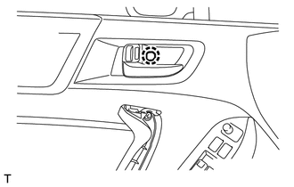
INSTALL POWER WINDOW REGULATOR MASTER SWITCH ASSEMBLY WITH FRONT DOOR ARMREST BASE PANEL (for Driver Side)
-
Install the power window regulator master switch assembly with front door armrest base panel with the 4 screws.
-
-
INSTALL POWER WINDOW REGULATOR SWITCH ASSEMBLY WITH FRONT DOOR ARMREST BASE PANEL (for Front Passenger Side)
-
Install the power window regulator switch assembly with front door armrest base panel with the 4 screws.
-
-
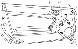
INSTALL FRONT DOOR INSIDE HANDLE SUB-ASSEMBLY
-
Engage the 2 guides.
-
Install the front door inside handle sub-assembly to the front door trim board sub-assembly with the 2 screws.
-
-
INSTALL FRONT DOOR TRIM BOARD SUB-ASSEMBLY
-
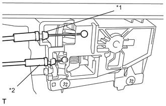
Text in Illustration *1 Front Door Inside Locking Cable Assembly *2 Front Door Lock Remote Control Cable Assembly Connect the front door lock remote control cable assembly and front door inside locking cable assembly to the front door inside handle.
-
Connect each connector.
-
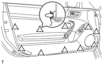
Engage the 10 clips and install the front door trim board sub-assembly.
-
Engage the clip and install the 3 screws.
-
Engage the claw and install the cap.
-
-
INSTALL COURTESY LIGHT ASSEMBLY (w/ Courtesy Light)
-
INSTALL DOOR ARMREST COVER
-
Engage the guide and 7 claws, and install the door armrest cover.
-
-
CONNECT CABLE TO NEGATIVE BATTERY TERMINAL
- Torque:
- 6.0 N*m { 61 kgf*cm, 53 in.*lbf }
-
INITIALIZE POWER WINDOW CONTROL SYSTEM
-
INSPECT POWER WINDOW