ROOF HEADLINING REMOVAL

CAUTION / NOTICE / HINT
The necessary procedures (adjustment, calibration, initialization or registration) that must be performed after parts are removed and installed, or replaced during roof headlining removal/installation are shown below.
| Replaced Part or Performed Procedure | Necessary Procedure | Effect/Inoperative Function when Necessary Procedure not Performed | Link |
|---|---|---|---|
| Disconnect cable from negative battery terminal | Perform steering sensor zero point calibration | Lane departure alert system (w/ Steering Control) | |
| Pre-collision system | |||
| Memorize steering angle neutral point | Parking assist monitor system |
CAUTION:
Some of these service operations affect the SRS airbag system. Read the precautionary notices concerning the SRS airbag system before servicing.
PROCEDURE
-
REMOVE FRONT SEAT ASSEMBLY (for Manual Seat)
-
REMOVE FRONT SEAT ASSEMBLY (for Power Seat)
-
REMOVE REAR SEAT ASSEMBLY (for Fixed Seat Type)
-
REMOVE REAR SEAT ASSEMBLY (for Fold Down Seat Type)
-
REMOVE REAR SEAT ASSEMBLY (for Reclining Seat Type)
-
REMOVE FRONT DOOR SCUFF PLATE LH
-
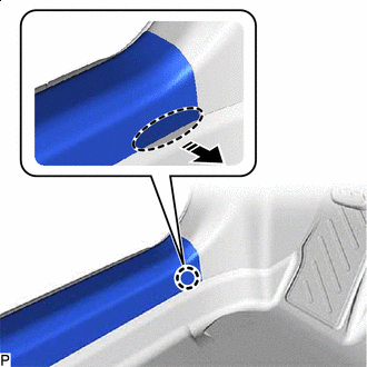

Place Hand Here 
Remove in this Direction Disengage the claw as shown in the illustration.
Tech Tips
Use the same procedure for the front side and rear side.
-
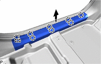
Remove in this Direction Disengage the 8 claws and guide to remove the front door scuff plate LH as shown in the illustration.
-
-
REMOVE COWL SIDE TRIM SUB-ASSEMBLY LH
-
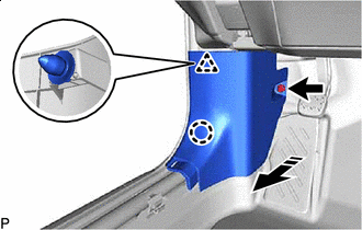
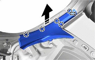
Remove in this Direction Remove the clip.
-
Disengage the claw and clip to remove the cowl side trim sub-assembly LH as shown in the illustration.
-
-
REMOVE FRONT DOOR OPENING TRIM WEATHERSTRIP LH
-
REMOVE FRONT PILLAR GARNISH LH (w/o Curtain Shield Airbag)
-

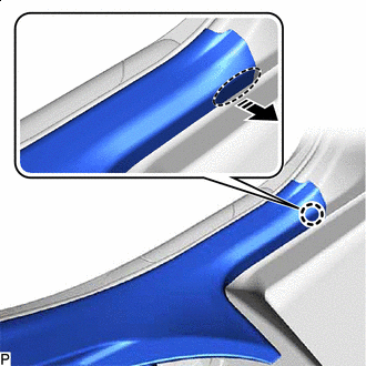
Protective Tape Apply protective tape around the front pillar garnish LH as shown in the illustration.
-
Place Hand Here Remove in this Direction Pull the upper part of the front pillar garnish LH as shown in the illustration to disengage the 2 clips.
-
Remove in this Direction Disengage the 2 guides to remove the front pillar garnish LH as shown in the illustration.
-
-
REMOVE FRONT PILLAR GARNISH LH (w/ Curtain Shield Airbag)
-
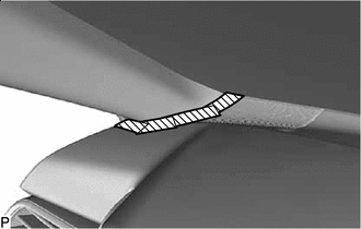
Protective Tape Apply protective tape around the front pillar garnish LH as shown in the illustration.
-
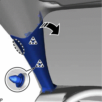
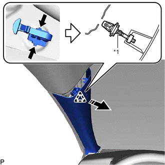
*1 Front Pillar Garnish Clip Place Hand Here Remove in this Direction Pull the upper part of the front pillar garnish LH toward the inside of the cabin to disengage the clip and the front pillar garnish LH from the base of the front pillar garnish clip.
Tech Tips
Let the front pillar garnish LH hang from the front pillar garnish clip.
-
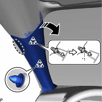
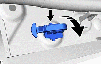
*1 Front Pillar Garnish Clip Remove in this Direction While pushing the tabs of the front pillar garnish clip as shown in the illustration, disengage it.
Note
-
The front pillar garnish clip is reusable if it is not damaged.
-
If the front pillar garnish clip is damaged, replace it with a new one.
Tech Tips
When the front pillar garnish clip cannot be disengaged easily:
-
Move in this Direction While pushing the tab of the front pillar garnish clip shown in the illustration with your finger, move the front pillar garnish clip in the direction shown in the illustration.
-
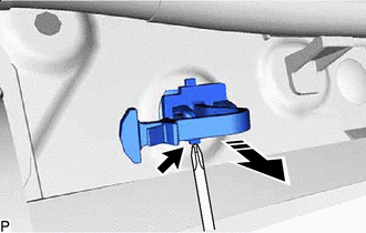
Pull in this Direction While pulling the front pillar garnish clip as shown in the illustration, push the tab of the front pillar garnish clip shown in the illustration with a screwdriver and disengage the front pillar garnish clip.
-
-
w/o Front No. 3 Speaker:
-
Remove in this Direction Disengage the 2 guides to remove the front pillar garnish LH as shown in the illustration.
-
-
w/ Front No. 3 Speaker:
-
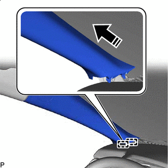
Disengage the 2 guides as shown in the illustration.
-
Disconnect the connector to remove the front pillar garnish LH.
-
-
Remove the clip from the front pillar garnish LH.
-
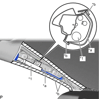
*1 Curtain Shield Airbag Assembly LH *a Protective Cover *b Adhesive Tape Protect the curtain shield airbag assembly LH.
-
Cover the curtain shield airbag assembly LH with a piece of cloth or nylon and secure the edges of the cover with tape as shown in the illustration.
Note
Cover the curtain shield airbag assembly LH with a protective cover as soon as the front pillar garnish LH is removed.
-
-
-
REMOVE REAR DOOR SCUFF PLATE LH
-
Place Hand Here Remove in this Direction Disengage the claw as shown in the illustration.
-
Remove in this Direction Disengage the 5 claws and guide to remove the rear door scuff plate LH as shown in the illustration.
-
-
REMOVE REAR DOOR OPENING TRIM WEATHERSTRIP LH
-
REMOVE LAP BELT OUTER ANCHOR COVER (for LH Side)
-
DISCONNECT FRONT SEAT OUTER BELT ASSEMBLY LH
-
REMOVE LOWER CENTER PILLAR GARNISH LH
-
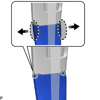
Place Hand Here Remove in this Direction Disengage the 2 claws as shown in the illustration.
-
Place Hand Here Remove in this Direction Disengage the 3 clips to remove the lower center pillar garnish LH as shown in the illustration.
-
-
REMOVE UPPER CENTER PILLAR GARNISH LH
-
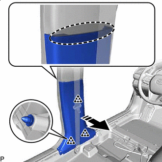
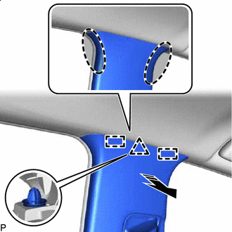
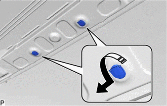
Using a clip remover, remove the 2 clips.
-
Place Hand Here Remove in this Direction Disengage the guide as shown in the illustration.
-
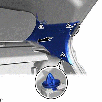
Place Hand Here Remove in this Direction Disengage the clip and 2 guides to remove the upper center pillar garnish LH as shown in the illustration.
-
w/ Curtain Shield Airbag:
-
Remove the clip from the upper center pillar garnish LH.
-
-
-
REMOVE INNER ROOF SIDE GARNISH LH
-
Place Hand Here Remove in this Direction Disengage the 3 clips as shown in the illustration.
-
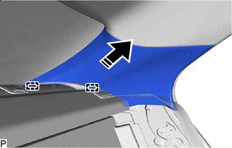
Remove in this Direction Disengage the 2 guides to remove the inner roof side garnish LH as shown in the illustration.
-
w/ Curtain Shield Airbag:
-
Remove the 3 clips from the inner roof side garnish LH.
-
-
-
REMOVE FRONT DOOR SCUFF PLATE RH
Tech Tips
Use the same procedure as for the LH side.
-
REMOVE COWL SIDE TRIM SUB-ASSEMBLY RH
Tech Tips
Use the same procedure as for the LH side.
-
REMOVE FRONT DOOR OPENING TRIM WEATHERSTRIP RH
Tech Tips
Use the same procedure as for the LH side.
-
REMOVE FRONT PILLAR GARNISH RH (w/o Curtain Shield Airbag)
Tech Tips
Use the same procedure as for the LH side.
-
REMOVE FRONT PILLAR GARNISH RH (w/ Curtain Shield Airbag)
Tech Tips
Use the same procedure as for the LH side.
-
REMOVE REAR DOOR SCUFF PLATE RH
Tech Tips
Use the same procedure as for the LH side.
-
REMOVE REAR DOOR OPENING TRIM WEATHERSTRIP RH
Tech Tips
Use the same procedure as for the LH side.
-
REMOVE LAP BELT OUTER ANCHOR COVER (for RH Side)
Tech Tips
Use the same procedure as for the LH side.
-
DISCONNECT FRONT SEAT OUTER BELT ASSEMBLY RH
Tech Tips
Use the same procedure as for the LH side.
-
REMOVE LOWER CENTER PILLAR GARNISH RH
Tech Tips
Use the same procedure as for the LH side.
-
REMOVE UPPER CENTER PILLAR GARNISH RH
Tech Tips
Use the same procedure as for the LH side.
-
REMOVE INNER ROOF SIDE GARNISH RH
Tech Tips
Use the same procedure as for the LH side.
-
REMOVE INSTRUMENT PANEL SAFETY PAD SUB-ASSEMBLY
-
REMOVE TRANSMISSION FLOOR SHIFT ASSEMBLY
for UA80E:
for UB80E:
for U760E:
-
REMOVE ROOF CONSOLE BOX ASSEMBLY
-
REMOVE ROOM LIGHT ASSEMBLY (for Bulb Type)
-
REMOVE SPOT LIGHT ASSEMBLY (for LED Type)
-
REMOVE RAIN SENSOR COVER (w/ Rain Sensor)
-
REMOVE INNER REAR VIEW MIRROR STAY HOLDER COVER (w/ Cover)
-
REMOVE NO. 2 FORWARD RECOGNITION COVER (w/ Pre-collision System)
-
REMOVE NO. 1 FORWARD RECOGNITION COVER (w/ Pre-collision System)
-
REMOVE ASSIST GRIP ASSEMBLY
Tech Tips
Use the same procedure for all assist grip assemblies.
-
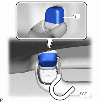
*a Cutout Insert SST into the cutout of the assist grip cover LH as shown in the illustration.
- SST
- 09813-00010
Note
To prevent the assist grip assembly from being damaged, make sure to insert SST straight into the cutout.
Tech Tips
Use the same procedure for the LH side and RH side.
-
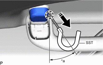
*a 30 to 45° Remove in this Direction Pull SST as shown in the illustration to disengage the claw.
Note
To prevent the assist grip assembly from being damaged, make sure to only pull SST as shown in the illustration.
Tech Tips
-
Use the same procedure for the claw on the other side of the assist grip cover LH.
-
Use the same procedure for the LH side and RH side.
-
-
Remove the assist grip cover LH.
Tech Tips
Use the same procedure for the LH side and RH side.
-
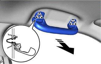
Remove in this Direction Disengage the 2 clips as shown in the illustration to remove the assist grip assembly.
-
Remove the 2 clips from the vehicle body.
-
-
REMOVE REAR ASSIST GRIP ASSEMBLY LH
Tech Tips
Use the same procedure as for the assist grip assembly.
-
REMOVE REAR ASSIST GRIP ASSEMBLY RH
Tech Tips
Use the same procedure as for the assist grip assembly.
-
REMOVE VISOR BRACKET COVER LH
-
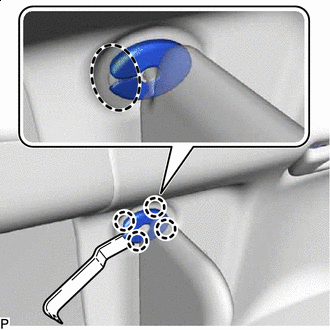
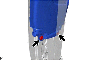
Insert Moulding Remover Here Using a moulding remover, disengage the 4 claws as shown in the illustration and remove the visor bracket cover LH.
-
-
REMOVE VISOR ASSEMBLY LH
-
for "TORX" Screw:
-
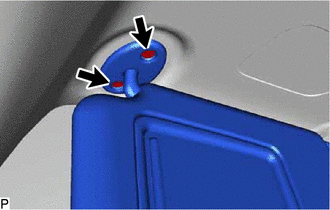
Using a T25 "TORX" socket wrench, remove the 2 screws.
-
-
except "TORX" Screw:
-
Remove the 2 screws.
-
-
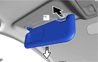
*1 Visor Holder LH Remove in this Direction (1) 
Remove in this Direction (2) Pull the visor assembly LH in the direction indicated by the arrow (1) shown in the illustration to disconnect it from the visor holder LH.
-
Pull the visor assembly LH in the direction indicated by the arrow (2) shown in the illustration to remove it.
-
-
REMOVE VISOR HOLDER LH
-
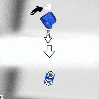
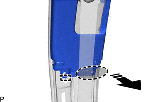
*a 45° Remove in this Direction (1) Remove in this Direction (2) Turn the visor holder LH approximately 45° and pull it out as indicated by the arrows, in the order shown in the illustration.
-
Disengage the 2 claws to remove the visor holder LH.
-
-
REMOVE VISOR BRACKET COVER RH
Tech Tips
Use the same procedure as for the LH side.
-
REMOVE VISOR ASSEMBLY RH
Tech Tips
Use the same procedure as for the LH side.
-
REMOVE VISOR HOLDER RH
Tech Tips
Use the same procedure as for the LH side.
-
REMOVE SUN ROOF OPENING TRIM MOULDING (for Moon Roof)
-
Remove the sun roof opening trim moulding.
-
-
REMOVE ROOF HEADLINING ASSEMBLY
-
for Windshield Glass Side:
-
w/ EC Mirror:
-
Disconnect each connector.
-
-
w/ Pre-collision System:
-
Disconnect the 2 connectors.
-
-
-
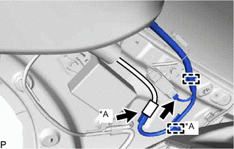
for Front Pillar LH Side:
-
Remove the protective cover.
-
Disconnect each connector.
-
Using a clip remover, disengage the 4 clamps.
-
Install the protective cover.
-
-
for Front Pillar RH Side:
-
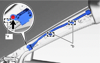
*a Guide *b Clamp Remove the protective cover.
-
Remove the bolt.
-
Disengage the guide to disconnect the connector bracket.
-
Using a clip remover, disengage the 2 clamps.
-
Install the protective cover.
-
-
for Rear Pillar LH Side:
-
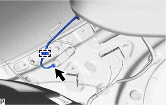
Disconnect the connector.
-
Using a clip remover, disengage the clamp.
-
-
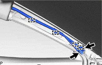
for Rear Pillar RH Side:
-
*A w/ Digital Audio Broadcasting Antenna Disconnect each connector.
-
Using a clip remover, disengage each clamp.
-
-
for Roof Side (for Normal Roof):
-
Using a clip remover, remove the 2 clips.
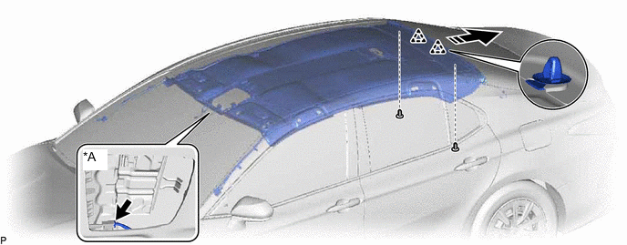
*A w/ Digital Television Antenna - - Remove in this Direction - - -
w/ Digital Television Antenna:
-
Disconnect the connector.
-
-
Slide the roof headlining assembly to disengage it from the 2 clips as shown in the illustration.
Tech Tips
Leave the 2 clips installed to the vehicle body.
-
-
for Roof Side (for Moon Roof):
-
Using a clip remover, remove the 2 clips.
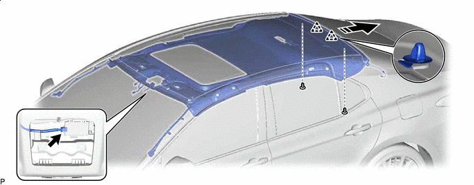
Remove in this Direction - - -
Disconnect the connector.
-
Slide the roof headlining assembly to disengage it from the 2 clips as shown in the illustration.
Tech Tips
Leave the 2 clips installed to the vehicle body.
-
-
for Roof Side (for Panoramic Moon Roof):
-
Using a clip remover, remove the 2 clips.
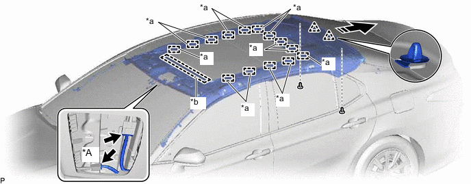
*A w/ Digital Television Antenna - - *a Fastener *b Guide Remove in this Direction - - -
Disconnect each connector.
-
Disengage the 14 fasteners and guide.
-
Slide the roof headlining assembly to disengage it from the 2 clips as shown in the illustration.
Tech Tips
Leave the 2 clips installed to the vehicle body.
-
-
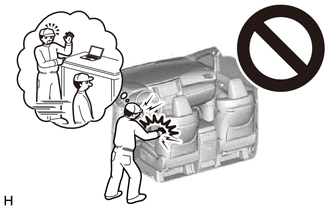
Remove the roof headlining assembly from the vehicle through the front door RH as shown in the illustration.
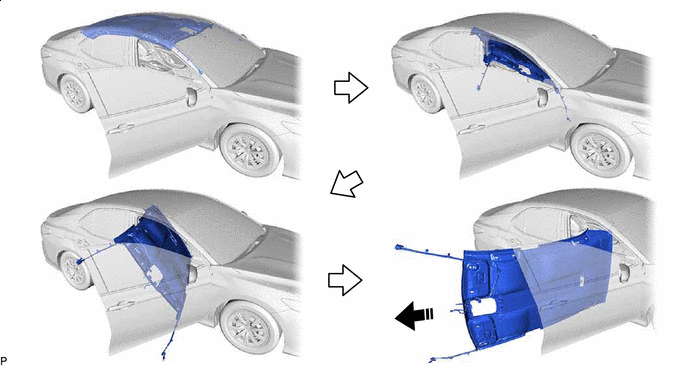
Remove in this Direction - - Note
Do not damage the roof headlining assembly or vehicle interior.
-
Remove in this Direction Remove the 2 clips from the vehicle body as shown in the illustration.
-