ENGINE ASSEMBLY INSTALLATION
CAUTION / NOTICE / HINT
As the engine assembly with transaxle is extremely heavy, the engine lifter may suddenly drop if the instructions listed in the repair manual are not followed. Therefore, always follow the instructions listed in the repair manual when performing this procedure.
for Manual Transaxle:
When the transaxle is removed, be sure to use a new clutch release with bearing cylinder and new installation bolts. Removal of the transaxle allows the compressed clutch release with bearing cylinder to return to its original position, and dust could damage the seal of the clutch release with bearing cylinder, possibly causing clutch fluid leaks.
Perform "Inspection After Repairs" after replacing the engine assembly, cylinder head sub-assembly, camshaft, No. 2 camshaft, camshaft timing gear assembly, camshaft timing exhaust gear assembly, piston sub-assembly or piston ring.
w/ Canister Pump Module
w/o Canister Pump Module
PROCEDURE
INSTALL ENGINE MOUNTING INSULATOR LH
Tip:Perform this procedure only when replacement of the engine mounting insulator LH is necessary.
Install the wire harness clamp bracket with the bolt.
7.7 N*m
79 kgf*cm
68 in.*lbf
-
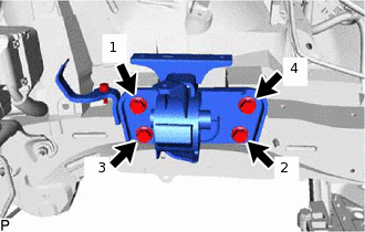
Temporarily install the engine mounting insulator LH with the 4 bolts.
Tighten the 4 bolts in the sequence shown in the illustration.
95 N*m
969 kgf*cm
70 ft.*lbf
INSTALL ENGINE MOUNTING SPACER
Tip:Perform this procedure only when replacement of the engine mounting spacer is necessary.
-
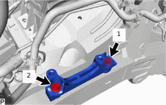
Temporarily install the engine mounting spacer with the 2 bolts.
Tighten the 2 bolts in the sequence shown in the illustration.
95 N*m
969 kgf*cm
70 ft.*lbf
-
INSTALL ENGINE MOUNTING INSULATOR SUB-ASSEMBLY RH
Tip:Perform this procedure only when replacement of the engine mounting insulator sub-assembly RH is necessary.
Install the radiator reservoir bracket with the bolt.
5.0 N*m
51 kgf*cm
44 in.*lbf
-
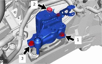
Temporarily install the engine mounting insulator sub-assembly RH with the 3 bolts.
Tighten the 3 bolts in the sequence shown in the illustration.
95 N*m
969 kgf*cm
70 ft.*lbf
INSTALL REAR ENGINE MOUNTING INSULATOR
Tip:Perform this procedure only when replacement of the rear engine mounting insulator is necessary.
-
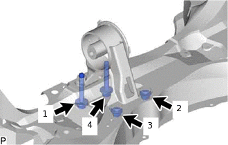
Temporarily install the rear engine mounting insulator with the 2 bolts and 2 nuts.
Tighten the 2 bolts and 2 nuts in the sequence shown in the illustration.
95 N*m
969 kgf*cm
70 ft.*lbf
-
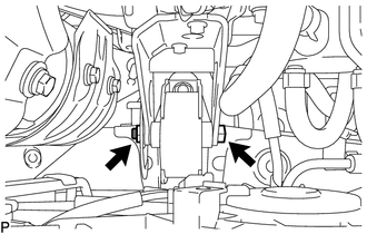
INSTALL FRONT ENGINE MOUNTING INSULATOR
Tip:Perform this procedure only when replacement of the front engine mounting insulator is necessary.
Install the front engine mounting insulator with the 2 bolts.
95 N*m
969 kgf*cm
70 ft.*lbf
INSTALL ENGINE HANGER
REMOVE ENGINE FROM ENGINE STAND
Note:Pay attention to the angle of the sling device as the engine assembly or engine hangers may be damaged or deformed if the angle is incorrect.
With the exception of installing the engine assembly to an engine stand or removing the engine assembly from an engine stand, do not perform any work on the engine while it is suspended, as doing so is dangerous.
Attach a sling device and hang the engine with a chain block.
Lift the engine and remove it from the engine stand.
FIX ENGINE ASSEMBLY
INSTALL ENGINE WIRE
Install the engine wire to the engine.
INSTALL CLUTCH RELEASE WITH BEARING CYLINDER ASSEMBLY (for Manual Transaxle)
INSTALL DRIVE PLATE AND RING GEAR SUB-ASSEMBLY (for Automatic Transaxle)
INSTALL FLYWHEEL SUB-ASSEMBLY (for Manual Transaxle)
INSTALL CLUTCH DISC ASSEMBLY (for Manual Transaxle)
INSTALL CLUTCH COVER ASSEMBLY (for Manual Transaxle)
INSPECT AND ADJUST CLUTCH COVER ASSEMBLY (for Manual Transaxle)
INSTALL AUTOMATIC TRANSAXLE ASSEMBLY (for Automatic Transaxle)
for 2WD
for 4WD/AWD
INSTALL MANUAL TRANSAXLE ASSEMBLY (for Manual Transaxle)
for 2WD
for 4WD/AWD
INSTALL TRANSFER ASSEMBLY (for 4WD/AWD)
INSTALL STARTER ASSEMBLY
INSTALL ENGINE ASSEMBLY WITH TRANSAXLE
Temporarily install the front engine mounting insulator with the through bolt and nut.
-
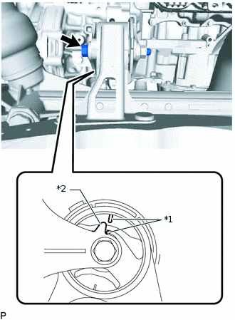
*1
Alignment Mark
*2
Protrusion
Temporarily install the front suspension crossmember with the through bolt.
Tip:When installing the suspension crossmember, align the protrusion of the engine mounting bracket with the alignment mark of the engine mounting insulator.
Place the engine on an engine lifter.
Tip:Place the engine on wooden blocks or equivalent so that the engine is level.
Operate the engine lifter and install the engine to the vehicle.
CAUTION:Do not raise the engine more than necessary. If the engine is raised excessively, the vehicle may also be lifted up.
Note:Make sure that the engine is clear of all wiring and hoses.
While raising the engine into the vehicle, do not allow it to contact the vehicle.
-
Temporarily install the front suspension crossmember with the 2 bolts.
-
Temporarily install the member rear brace RH and LH with the 6 bolts.
Install the engine mounting insulator LH with the through bolt and nut.
56 N*m
571 kgf*cm
41 ft.*lbf
Note:While holding the bolt in place, tighten the nut.
-

Bolt

Nut
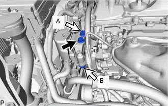
Install the engine mounting insulator RH with the bolt and 2 nuts.
for bolt and nut A
95 N*m
969 kgf*cm
70 ft.*lbf
for nut B
52 N*m
530 kgf*cm
38 ft.*lbf
-
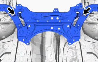
Tighten the 2 front suspension member bolts.
137 N*m
1397 kgf*cm
101 ft.*lbf
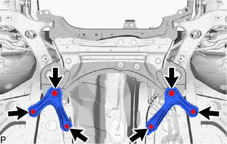
-
Bolt A
Bolt B
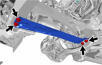
Tighten the 6 member rear brace bolts.
for bolt A
137 N*m
1397 kgf*cm
101 ft.*lbf
for bolt B
93 N*m
948 kgf*cm
69 ft.*lbf
Remove the 2 bolts and No. 1 and No. 2 engine hangers.
-
Bolt A
Bolt B
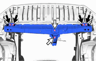
Install the front crossmember with the 6 bolts.
for bolt A
99 N*m
1010 kgf*cm
73 ft.*lbf
for bolt B
95 N*m
969 kgf*cm
70 ft.*lbf
Tighten the through bolt of the rear engine mounting insulator.
95 N*m
969 kgf*cm
70 ft.*lbf
Tip:Check that the protrusion of the engine mounting bracket is aligned with the alignment mark of the engine mounting insulator.
-
Tighten the through bolt and nut of the front engine mounting insulator.
145 N*m
1479 kgf*cm
107 ft.*lbf
Note:While holding the nut in place, tighten the through bolt.
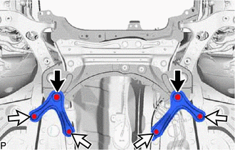
INSTALL FRONT SUSPENSION MEMBER REINFORCEMENT LH
-
Install the front suspension member reinforcement LH with the 4 bolts.
99 N*m
1010 kgf*cm
73 ft.*lbf
-
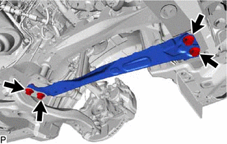
INSTALL FRONT SUSPENSION MEMBER REINFORCEMENT RH
-
Install the front suspension member reinforcement RH with the 4 bolts.
99 N*m
1010 kgf*cm
73 ft.*lbf
-
INSTALL PROPELLER WITH CENTER BEARING SHAFT ASSEMBLY (for 4WD/AWD)
INSTALL DRIVE PLATE AND TORQUE CONVERTER SETTING BOLT (for Automatic Transaxle)
for 2WD
for 4WD/AWD
INSTALL FLYWHEEL HOUSING UNDER COVER
Install the flywheel housing under cover.
INSTALL FRONT EXHAUST PIPE SUB-ASSEMBLY
INSTALL FRONT NO. 2 EXHAUST PIPE SUB-ASSEMBLY
CONNECT CLUTCH HOSE (for Manual Transaxle)
-
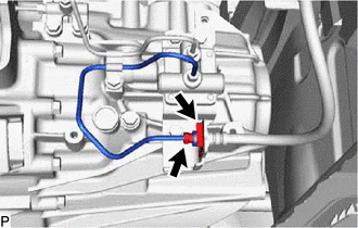
Temporarily install the clutch line.
Install the clutch hose with a new clip.
Using a union nut wrench, tighten the 2 clutch lines to the accumulator to flexible hose tube.
15 N*m
153 kgf*cm
11 ft.*lbf
Note:Use the formula to calculate special torque values for situations where a union nut wrench is combined with a torque wrench.
-
INSTALL DRIVE SHAFT BEARING BRACKET
Install the bracket with the 3 bolts.
63.7 N*m
650 kgf*cm
47 ft.*lbf
INSTALL FRONT DRIVE SHAFT HOLE SNAP RING LH
for 2WD
for 4WD/AWD
INSTALL FRONT DRIVE SHAFT ASSEMBLY LH
for 2WD
for 4WD/AWD
INSTALL FRONT DRIVE SHAFT ASSEMBLY RH
for 2WD
for 4WD/AWD
CONNECT FRONT LOWER NO. 1 SUSPENSION ARM SUB-ASSEMBLY LH
CONNECT FRONT LOWER NO. 1 SUSPENSION ARM SUB-ASSEMBLY RH
Tip:Use the same procedure described for the LH side.
CONNECT TIE ROD END SUB-ASSEMBLY LH
CONNECT TIE ROD END SUB-ASSEMBLY RH
Tip:Use the same procedure described for the LH side.
CONNECT FRONT STABILIZER LINK ASSEMBLY LH
CONNECT FRONT STABILIZER LINK ASSEMBLY RH
Tip:Use the same procedure described for the LH side.
CONNECT FRONT SPEED SENSOR LH
CONNECT FRONT SPEED SENSOR RH
Tip:Use the same procedure described for the LH side.
INSTALL FRONT AXLE SHAFT NUT LH
INSTALL FRONT AXLE SHAFT NUT RH
Tip:Use the same procedure described for the LH side.
CONNECT NO. 1 STEERING COLUMN HOLE COVER SUB-ASSEMBLY
CONNECT NO. 2 STEERING INTERMEDIATE SHAFT ASSEMBLY
INSTALL COLUMN HOLE COVER SILENCER SHEET
CONNECT TRANSMISSION CONTROL CABLE ASSEMBLY (for Manual Transaxle)
Connect the 2 transmission control cables with 2 new clips.
Install the 2 new clips.
CONNECT TRANSMISSION CONTROL CABLE ASSEMBLY (for Automatic Transaxle)
Connect the transmission control cable to the control cable bracket with a new clip.
Connect the transmission control cable to the control shaft lever with the nut.
12 N*m
122 kgf*cm
9 ft.*lbf
CONNECT WIRE HARNESS AND HOSE
for Automatic Transaxle:
Connect the heater hose to the cylinder head sub-assembly, and slide the clip to secure it.
Connect the heater hose to the No. 1 water by-pass pipe, and slide the clip to secure it.
for Manual Transaxle:
Attach the heater hose to the clamp.
Connect the heater hose to the cylinder head sub-assembly, and slide the clip to secure it.
Connect the heater hose to the No. 1 water by-pass pipe, and slide the clip to secure it.
Connect the vacuum hose to the No. 1 hose to hose tube, and slide the clip to secure it.
Connect the wire harness with the bolt.
11.4 N*m
116 kgf*cm
8 ft.*lbf
Connect the 2 connectors, attach the 2 claws to the engine room No. 1 relay block and connect the wire harness.
Connect the wire harness to the engine room No. 1 relay block with the nut.
12.8 N*m
131 kgf*cm
9 ft.*lbf
Connect the wire harness with the bolt.
8.4 N*m
86 kgf*cm
74 in.*lbf
Connect the 2 clamps and wire harness.
Connect the clamp.
Connect the starter wire with the nut.
9.8 N*m
100 kgf*cm
87 in.*lbf
Install the terminal cap.
CONNECT FUEL TUBE SUB-ASSEMBLY
Connect the fuel tube connector.
Install the No. 1 fuel pipe clamp.
INSTALL TRANSMISSION OIL COOLER (for Automatic Transaxle)
for 2WD
for 4WD/AWD
CONNECT SUCTION HOSE SUB-ASSEMBLY
CONNECT DISCHARGE HOSE SUB-ASSEMBLY
CONNECT RADIATOR HOSE SUB-ASSEMBLY
INSTALL RADIATOR HOSE HOSE CLAMP
CONNECT NO. 2 RADIATOR HOSE
INSTALL GENERATOR ASSEMBLY
INSTALL FAN AND GENERATOR V BELT
CONNECT RADIATOR RESERVOIR ASSEMBLY
INSTALL ECM
INSTALL BATTERY BRACKET REINFORCEMENT
INSTALL FRONT BATTERY BRACKET
INSTALL BATTERY TRAY
INSTALL BATTERY
INSTALL BATTERY INSULATOR
INSTALL BATTERY CLAMP SUB-ASSEMBLY
INSTALL AIR CLEANER CASE
INSTALL AIR CLEANER CAP SUB-ASSEMBLY
CONNECT CABLE TO NEGATIVE BATTERY TERMINAL
Note:When disconnecting the cable, some systems need to be initialized after the cable is reconnected.
CHARGE AIR CONDITIONING SYSTEM WITH REFRIGERANT
ADD MANUAL TRANSAXLE OIL (for Manual Transaxle)
for 2WD
for 4WD/AWD
INSPECT MANUAL TRANSAXLE OIL (for Manual Transaxle)
for 2WD
for 4WD/AWD
ADD AUTOMATIC TRANSAXLE FLUID (for Automatic Transaxle)
for 2WD
for 4WD/AWD
ADD TRANSFER OIL (for 4WD/AWD)
ADD ENGINE COOLANT
ADD ENGINE OIL
INSPECT FOR FUEL LEAK
INSPECT FOR COOLANT LEAK
INSPECT FOR OIL LEAK
INSPECT FOR EXHAUST GAS LEAK
INSPECT FOR REFRIGERANT LEAK
INSPECT IGNITION TIMING
INSPECT ENGINE IDLE SPEED
INSPECT CO/HC
ADJUST FRONT WHEEL ALIGNMENT
INSTALL NO. 2 ENGINE UNDER COVER (w/ Cover)
Install the No. 2 engine under cover with the clip and bolt.
5.5 N*m
56 kgf*cm
49 in.*lbf
INSTALL FRONT FLOOR COVER (w/ Cover)
INSTALL NO. 1 ENGINE COVER SUB-ASSEMBLY
INSTALL REAR ENGINE UNDER COVER RH
Install the rear engine under cover RH with the 3 clips.
INSTALL REAR ENGINE UNDER COVER LH
for Half Cover Type:
Install the rear engine under cover LH with the 3 clips.
for Full Cover Type:
Install the rear engine under cover LH with the 2 clips.
INSTALL NO. 1 ENGINE UNDER COVER
for Half Cover Type:
Install the No. 1 engine under cover with the 6 screws and 5 clips.
for Full Cover Type:
Install the No. 1 engine under cover with the 2 screws, 4 bolts and 8 clips.