CONDENSER REMOVAL
PROCEDURE
-
PRECAUTION
Note
After turning the power switch off, waiting time may be required before disconnecting the cable from the negative (-) auxiliary battery terminal. Therefore, make sure to read the disconnecting the cable from the negative (-) auxiliary battery terminal notices before proceeding with work Click here.
-
RECOVER REFRIGERANT FROM REFRIGERATION SYSTEM (for HFC-134a(R134a))
-
RECOVER REFRIGERANT FROM REFRIGERATION SYSTEM (for HFO-1234yf(R1234yf))
-
REMOVE DECK BOARD ASSEMBLY
-
REMOVE NO. 1 DECK BOARD
-
REMOVE NO. 2 DECK BOARD
-
REMOVE REAR DECK FLOOR BOX
-
REMOVE DECK FLOOR BOX RH
-
DISCONNECT CABLE FROM NEGATIVE AUXILIARY BATTERY TERMINAL
Note
When disconnecting the cable, some systems need to be initialized after the cable is reconnected Click here.
-
REMOVE FRONT BUMPER ASSEMBLY
-
REMOVE MILLIMETER WAVE RADAR SENSOR ASSEMBLY (w/ Dynamic Radar Cruise Control System)
-
REMOVE NO. 1 MILLIMETER WAVE RADAR SENSOR BRACKET (w/ Dynamic Radar Cruise Control System)
-
Remove the 2 bolts.
-
Disengage the 2 guides and remove the No. 1 millimeter wave radar sensor bracket.
-
-
REMOVE NO. 1 INVERTER BRACKET
-
DISCONNECT NO. 5 INVERTER COOLING HOSE
-
Using pliers, grip the claws of the clip and slide the clip to disconnect the No. 5 inverter cooling hose.
Note
-
After disconnecting the No. 5 inverter cooling hose, immediately seal the openings of the hose and the condenser assembly with receiver and hybrid radiator assembly using vinyl tape to prevent entry of foreign matter.
-
Do not apply excessive force to the No. 5 inverter cooling hose.
-
Prepare a drain pan or cloth in case the coolant leaks.
-
-
-
DISCONNECT NO. 1 INVERTER COOLING HOSE
-
Using pliers, grip the claws of the clip and slide the clip to disconnect the No. 1 inverter cooling hose.
Note
-
After disconnecting the No. 1 inverter cooling hose, immediately seal the openings of the hose and the condenser assembly with receiver and hybrid radiator assembly using vinyl tape to prevent entry of foreign matter.
-
Do not apply excessive force to the No. 1 inverter cooling hose.
-
Prepare a drain pan or cloth in case the coolant leaks.
-
-
-
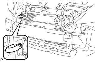
DISCONNECT NO. 1 COOLER REFRIGERANT DISCHARGE HOSE
-
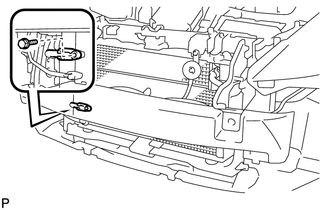
Remove the bolt and disconnect the No. 1 cooler discharge hose.
-
Remove the O-ring from the No. 1 cooler discharge hose.
Note
Seal the openings of the disconnected parts using vinyl tape to prevent entry of moisture and foreign matter.
-
-
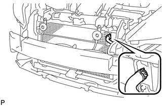
DISCONNECT AIR CONDITIONER TUBE AND ACCESSORY ASSEMBLY
-
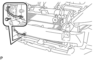
Remove the bolt and disconnect the air conditioner tube and accessory assembly.
-
Remove the O-ring from the air conditioner tube and accessory assembly.
Note
Seal the openings of the disconnected parts using vinyl tape to prevent entry of moisture and foreign matter.
-
-
REMOVE HOOD LOCK SUPPORT SUB-ASSEMBLY
-
REMOVE NO. 2 FAN SHROUD
-
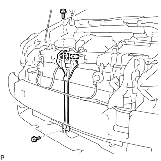
REMOVE CONDENSER ASSEMBLY WITH RECEIVER
-
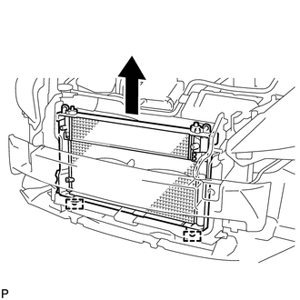
Disengage the 2 guides and remove the condenser assembly with receiver and hybrid radiator assembly as shown in the illustration.
-
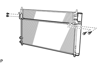
Remove the 4 bolts and hybrid radiator assembly from the condenser assembly with receiver.
-